Gaz analyzer with protection for optical components

a technology of optical components and gas analyzers, applied in the direction of material analysis through optical means, measurement devices, instruments, etc., can solve the problems of inability to provide lack of easy calibration and validation, and inability to detect the presence of specific gas analysis components, etc., to prevent contamination of optical analyzer systems, fast response time, and the effect of handling high dust loads

Inactive Publication Date: 2020-08-20
NEO MONITORS AS
View PDF0 Cites 1 Cited by
  • Summary
  • Abstract
  • Description
  • Claims
  • Application Information

AI Technical Summary

Benefits of technology

[0014]The apparatus disclosed in the present invention has all the normal general benefits of an In Situ system, and adds the capability to prevent contamination of an optical analyzer system, and the capability to handle high dust loads with a fast response time. The system also is simple to calibrate or validate during operation behind the pressure control chamber filter walls. The layout of the system is designed so it is capable of taking advantage of existing apparatus, and the expected new releases of light based analyzers capable of measuring new gas components, e.g., developments within laser based analyzers and others.
[0015]The apparatus of the present invention comprises an analyzer positioned outside the environment to be analyzed, and an elongate volume with walls that filters the medium to be analyzed so that dust and other particles are prevented from entering the volume. In front of an optical face is a cushion body of protecting gas, e.g., air, or a gas such as nitrogen. Between this cushion and the medium to be analyzed is a volume that extracts both the protecting gas and gas medium from the volume to be analyzed. In this way, the gas to be analyzed is forced through the filter while leaving unwanted dust and other particles on the outside of the filter. At the same time, optical faces are protected from possible contamination by a neutral cushion.

Problems solved by technology

However, In Situ systems in the past typically suffered in the areas of: being limited in handling high dust applications; having a lack of easy calibration and validation; having a limited number of gas analysis components measured in one unit; and having a lack of availability of specific gas analysis components.
However, Extractive systems in the past typically suffer in the areas of: having slower response time; potential impact on the measured gas; having higher cost of investment, installation, operation and maintenance; potential contamination of the sample system; a more complex system design and requiring a higher level of maintenance.
However none of these attempts have been able to find a successful solution which provides a fast response time with no impact on the measured gas in high dust level processes.
However, this can cause build-up of sediments of particulates in the measurement chamber.
However, optical surfaces are exposed to the process gas, which could lead to etching or otherwise damage the optical components in cases where the process gas contains corrosive or sticky gases.
However, this could in the normal case lead to dilution of the gas to be measured resulting in a false reading.

Method used


Image

  • Gaz analyzer with protection for optical components
  • Gaz analyzer with protection for optical components
  • Gaz analyzer with protection for optical components

Examples


Embodiment Construction

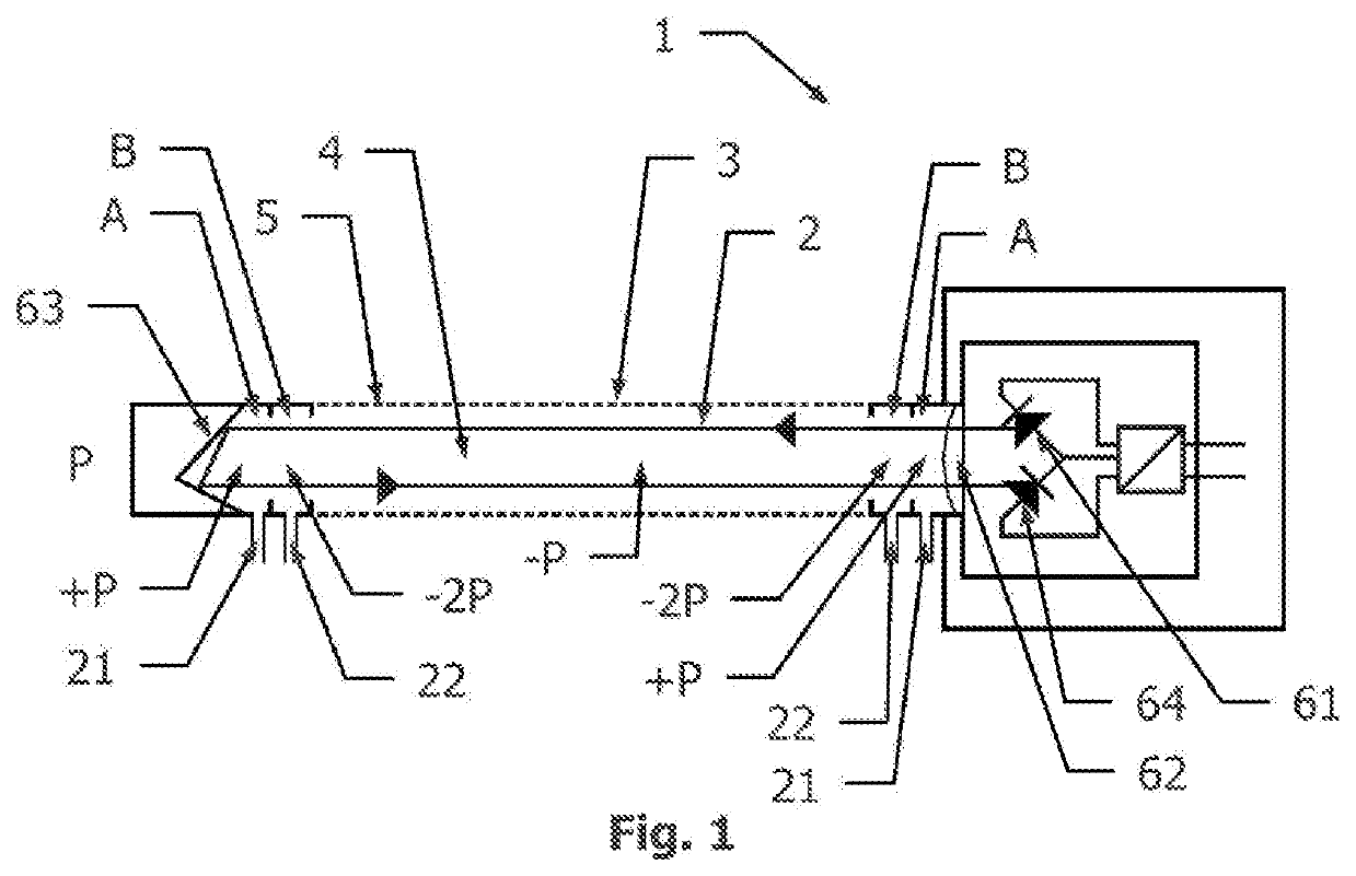
[0036]An embodiment of the apparatus of the present invention will now be discussed with reference to FIG. 1.

[0037]A filter wall 5 of a pipe 3 separates a surrounding process gas P to be analyzed from a measurement chamber 4 in which actual measurements are performed. Contrary to the part of the wall of pipe 3 surrounding the measurement chamber 4, the part of the wall of pipe 3 surrounding a purging chamber A and a suction chamber B is preferably non-permeable for gases.

[0038]A light based In Situ analyzer 1 is only able to operate if the light 2 can get through the process gas in the entire measuring path. If a dust load is too high, analysis is not possible.

[0039]A gas penetrable filter wall 5 of a pipe 3 can establish a dust free measuring path inside the pipe core, and solves the problem of passing light inside a process gas with high dust density.

[0040]The pressure in the measurement chamber 4 is lower than outside the pipe 3 in the surrounding process gas P. Besides the diffe...


PUM

PropertyMeasurementUnit
pressureaaaaaaaaaa
pressureaaaaaaaaaa
concentrationaaaaaaaaaa

Abstract

Gas analyzer and method for optical in situ measurements of a gaseous medium with a filter wall for keeping dust outside and a gas cushion to protect possible hazardous components in the gaseous medium.

Description

TECHNICAL FIELD[0001]The present invention relates to an optical gas analyzer for analysis of gaseous media, and in particular, to a gas analyzer comprising protection of optical components in a hostile medium.BACKGROUND OF THE INVENTION[0002]In any process relying on a combustion operation, it is important to know the concentration of some key gas components for process control, emission reporting and safety reasons. These gas components, such as Oxygen, Carbon Monoxide, Nitrogen Oxide, Hydrogen Sulphide, Sulphur Dioxide, Methane and others, can be measured at different locations representing different stages of the combustion process. This means that the conditions experienced at the different locations can vary substantially in terms of temperature level, dust load, and the concentration of the various gas components in the medium. However, regardless of the measuring point and the process conditions accuracy, response time and run factor of the analysis equipment has a major imp...

Claims


Application Information

Patent Timeline
Patent Type & Authority Applications(United States)
IPC IPC(8): G01N21/15G01N21/85
CPCG01N2021/8578G01N21/15G01N2021/8571G01N2021/151G01N21/85G01N21/8507G01N2021/1704
Inventor FLOOR, KARSTEN BRINK
Owner NEO MONITORS AS
Why Eureka
Try Eureka