Dye-sensitized solar cell comprising light collecting device panel

Inactive Publication Date: 2020-09-03
SOGANG UNIV RES & BUSINESS DEV FOUND
View PDF6 Cites 0 Cited by
  • Summary
  • Abstract
  • Description
  • Claims
  • Application Information

AI Technical Summary

Benefits of technology

The present patent is about a dye-sensitized solar cell that includes a light-collecting device panel containing a luminescent dye. The luminescent dye absorbs sunlight and converts it into light with a wavelength range that can be absorbed by conventional solar cells. This improves the photoelectric conversion efficiency of the solar cell. The patent also describes how the dye can be regulated to emit light at different wavelengths, and how the light can be efficiently propagated to the solar cell without energy loss. The solar cell can be used in various applications such as building windows and doors, automobiles, and soundproof walls. The technical effects of the patent are improved photoelectric conversion efficiency and increased durability of the dye-sensitized solar cell.

Problems solved by technology

However, the disclosed solar cell does not have high photoelectric conversion efficiency.

Method used


Image

  • Dye-sensitized solar cell comprising light collecting device panel
  • Dye-sensitized solar cell comprising light collecting device panel
  • Dye-sensitized solar cell comprising light collecting device panel

Examples


example 1

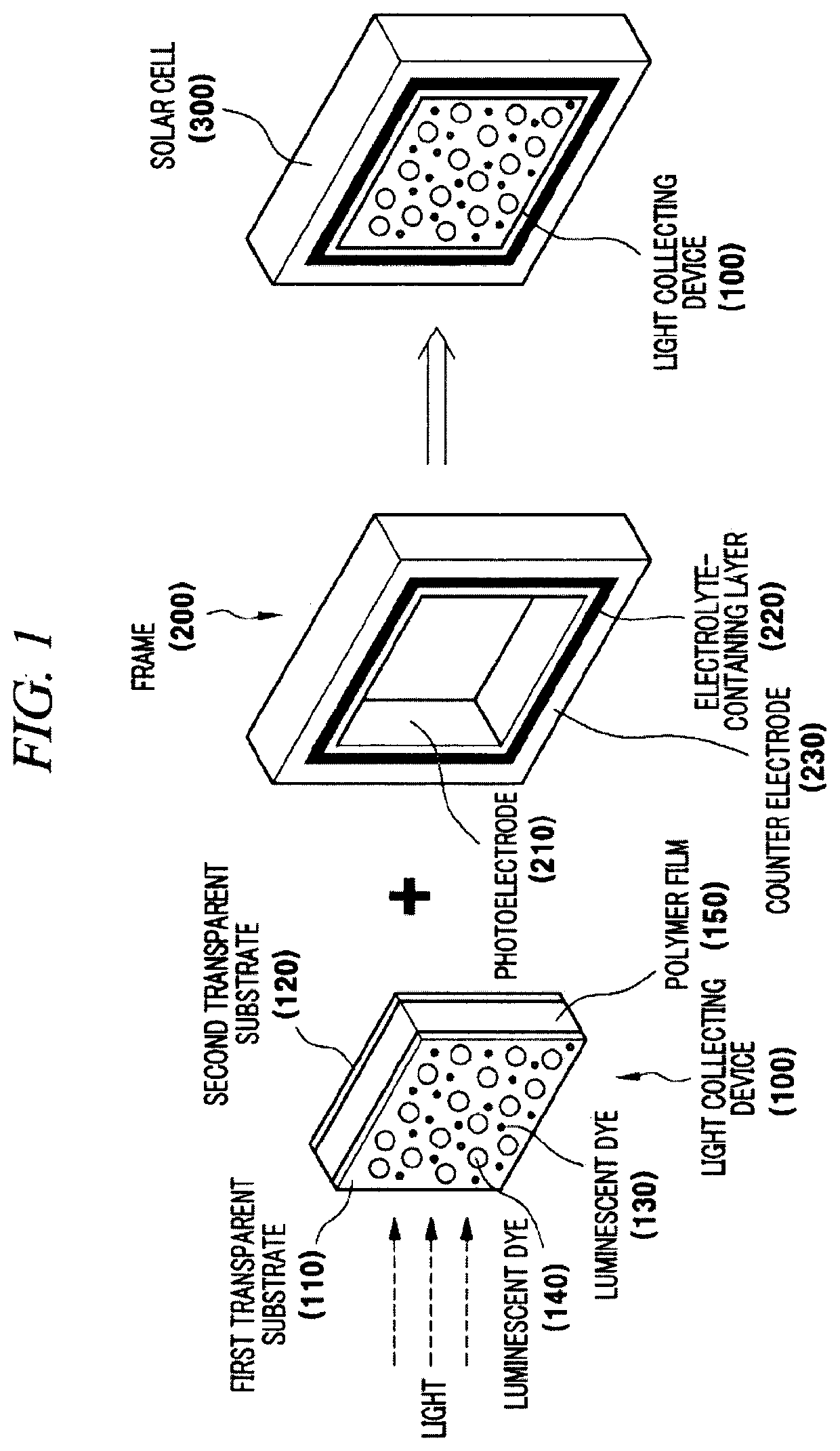
[0093]A dye-sensitized solar cell including a light-collecting device panel according to the present example was manufactured as follows. First, 9,10-bis(phenylethynyl)anthracene (BPEA) as a first luminescent dye and palladium(meso-tetraphenyl-tetrabenzoporphyrin) (PdTPBP) as a second luminescent dye were dispersed in chloroform and then added to and mixed with a polyurethane solution. Then, the polyurethane solution mixed with BPEA and PdTPBP was vortexed at room temperature and then rotary-evaporated at 40° C. to evaporate chloroform. Then, the solution from which chloroform was evaporated was dropped in two transparent glass substrates and hardened overnight to manufacture a light-collecting device panel.

[0094]The light-collecting device panel manufactured as described above was brought into contact with TiO2 photoelectrodes (containing a D205 dye) formed at respective four inner corners of a frame and then fixed with tape. The four photoelectrodes were simultaneously brought int...

example 2

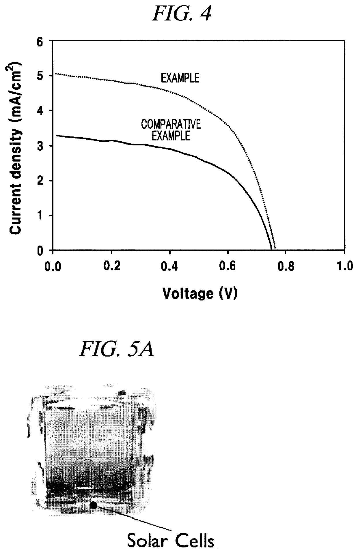
[0102]A dye-sensitized solar cell including a light-collecting device panel as shown in a photograph of FIG. 5A was manufactured by the method used in Example 1. The light-collecting device included a polyurethane polymer film containing a BPEA luminescent dye as a down-conversion luminescent dye and was composed of the polymer film and a glass panel covering the polymer film. Four dye-sensitized solar cells were connected to four corners of the light-collecting device. A dye-sensitized solar cell including a light-collecting device panel was finally implemented. As shown in a graph of FIG. 5B, the efficiency of the solar cell was measured as 9.1%.

example 3

[0103]A dye-sensitized solar cell including a light-collecting device panel with a different kind and concentration of luminescent dye was manufactured by the method used in Example 1. The light-collecting device contained both BPEA and PdTPBP and was manufactured with various concentrations of these luminescent dyes. The luminescence efficiency of the luminescent dyes at each concentration was measured and a result thereof was as shown in FIG. 6. Specifically, the BPEA and PdTPBP luminescent dyes were dispersed in chloroform solvents, respectively, to prepare luminescent dye solutions. These solutions were mixed with a polyurethane solution and then, the solvent was evaporated with a rotary evaporator to prepare a polymer film in which the luminescent dyes were dispersed uniformly. The luminescence efficiency of the luminescent dyes may vary depending on the concentrations of the luminescent dyes contained in the polymer film. Under the test conditions of the present example, a pol...


PUM

PropertyMeasurementUnit
Transparencyaaaaaaaaaa
Wavelengthaaaaaaaaaa
Luminescenceaaaaaaaaaa

Abstract

The present disclosure relates to a dye-sensitized solar cell including a light-collecting device panel disposed between a first transparent substrate and a second transparent substrate, including a polymer film containing a luminescent dye; and a frame formed in contact with a corner of the light-collecting device panel, including a photoelectrode containing a dye.

Description

TECHNICAL FIELD[0001]The present disclosure relates to a dye-sensitized solar cell including a light-collecting device panel containing a luminescent dye.BACKGROUND[0002]In general, a solar cell is a device that converts light energy of the sun into electric energy. The solar cell is a device that generates electricity using sunlight which is an infinite energy source. A silicon solar cell as a representative solar cell has already been widely used in our lives, and a dye-sensitized solar cell has been researched as a next-generation solar cell.[0003]A representative example of dye-sensitized solar cells is presented by Gratzel et al. from Switzerland (refer to U.S. Pat. No. 5,350,644). In the structural aspect, one of two electrodes of the dye-sensitized solar cell is a photoelectrode including a transparent conductive substrate having thereon a semiconductor oxide layer on which a photosensitive dye is adsorbed, and an electrolyte fills a gap between the two electrodes.[0004]The p...

Claims


Application Information

Patent Timeline
IPC IPC(8): H01G9/20B32B17/10H02S20/22H02S20/21
CPCB32B2307/422B32B17/10669H02S20/21B32B17/1077H01G9/209H01G9/2068B32B17/10036B32B2457/12B32B2307/412H01G9/2059H02S20/22B32B17/10B32B27/08B32B27/20Y02B10/10Y02E10/542H01G9/2031H01G9/2077
Inventor MOON, JUN HYUKHA, SU JIN
Owner SOGANG UNIV RES & BUSINESS DEV FOUND
Why Eureka
Try Eureka