Eureka AIR delivers breakthrough ideas for toughest innovation challenges, trusted by R&D personnel around the world.

Method for controlling a hydraulic system

a hydraulic system and hydraulic system technology, applied in the direction of fluidic programme control, mechanical equipment, servomotors, etc., can solve problems such as hydraulic system pressure oscillations

Active Publication Date: 2020-09-17
GM GLOBAL TECH OPERATIONS LLC
View PDF0 Cites 1 Cited by
  • Summary
  • Abstract
  • Description
  • Claims
  • Application Information

AI Technical Summary

Benefits of technology

The patent describes an electrohydraulic actuation system that uses a control valve to control the pressure and flow of fluid to a hydraulic actuator. A pressure sensor measures the pressure between the control valve and the actuator, and a target pressure module determines a target pressure for the actuator. An error module calculates an adjustment factor based on the difference between the target pressure and the current pressure, the rate of change in the difference, and the sum of the difference over time. An adjustment module applies this factor to the target pressure to correct for offset errors and reduce pressure oscillations. The technical effect of this system is to improve the accuracy and stability of the actuator control.

Problems solved by technology

In addition, pressure oscillations may occur in hydraulic systems that are designed to allow for fast reaction times due to reduced damping of the systems.

Method used


Image

  • Method for controlling a hydraulic system
  • Method for controlling a hydraulic system
  • Method for controlling a hydraulic system

Examples


Embodiment Construction

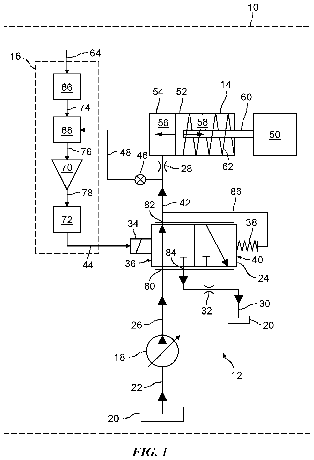
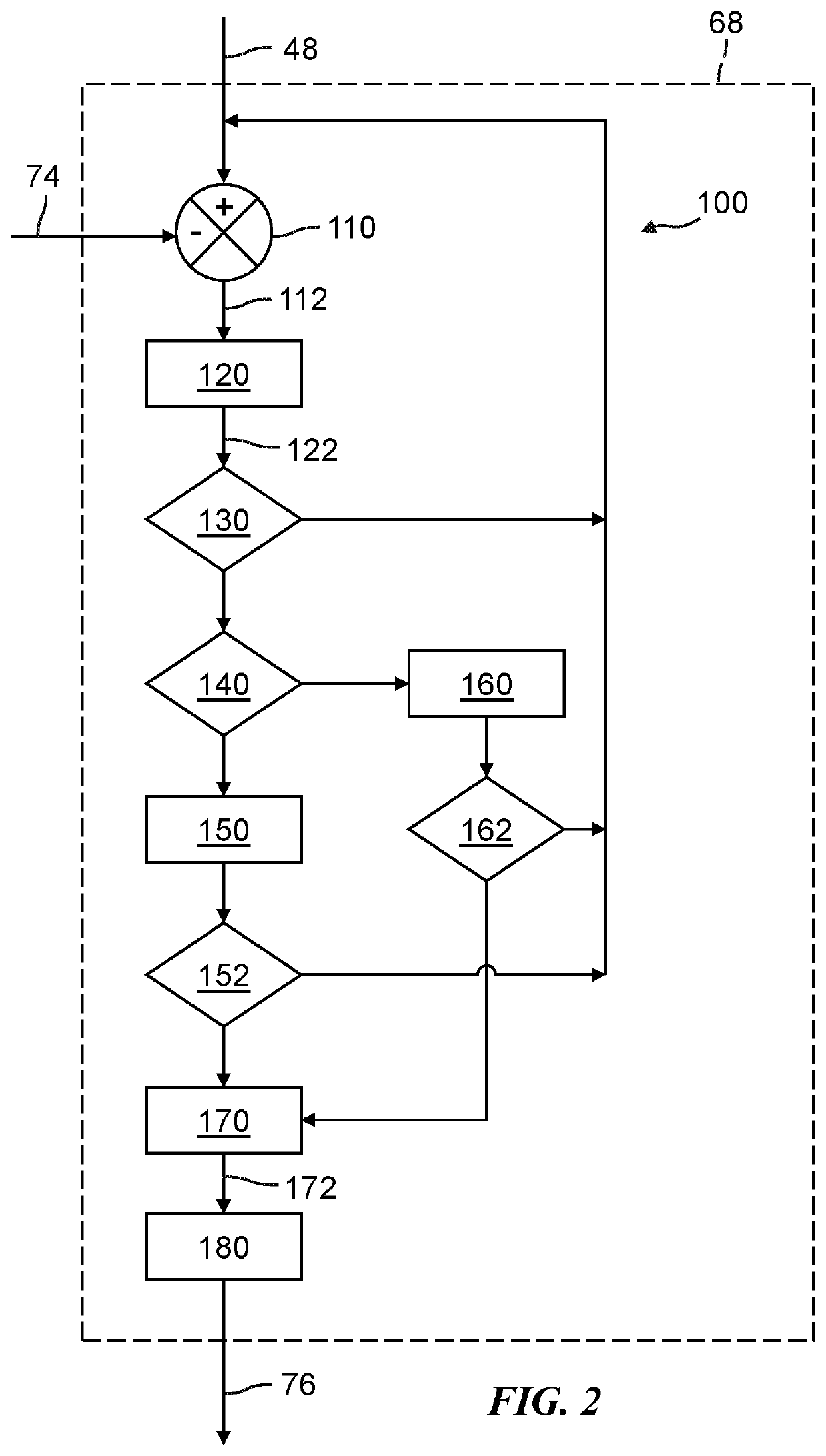
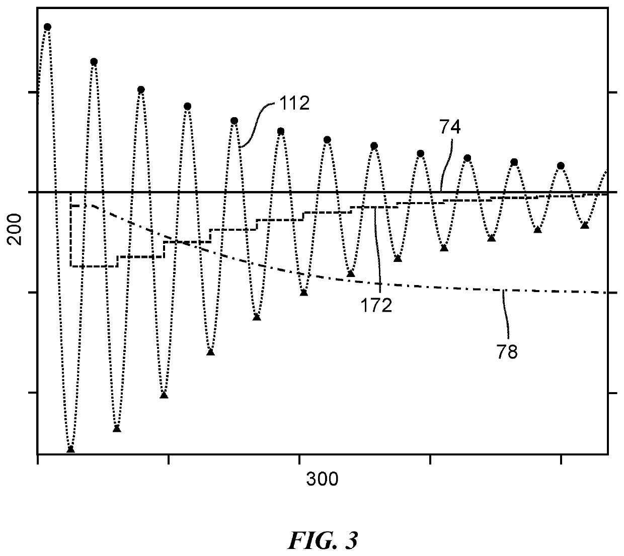
[0022]The method described herein can be used to provide closed loop control of a hydraulic system that includes an electrohydraulic control valve disposed in fluid communication between a source of pressured fluid and a hydraulic actuator, wherein pressure oscillations may frequently occur in the hydraulic fluid between the control valve and the hydraulic actuator. In particular, the method described herein can be used to control the pressure of the hydraulic fluid between the control valve and the hydraulic actuator (the actuator pressure) by rapidly and effectively correcting for offset errors between a target actuator pressure and a current actuator pressure, without amplifying pressure oscillations in the hydraulic fluid. The effective and rapid correction of such offset errors is accomplished by removing the magnitude of the pressure oscillations from the raw error signal to obtain a mean error value, and then applying a control algorithm including at least one of a proportion...


PUM


Abstract

A hydraulic system may include an electrohydraulic control valve disposed in fluid communication between a source of pressured fluid and a hydraulic actuator. The hydraulic system may be controlled to correct for offset errors between a target actuator pressure and a current actuator pressure output from the control valve, without amplifying pressure oscillations in the fluid between the control valve and the hydraulic actuator.

Description

INTRODUCTION[0001]Closed loop control systems, also referred to as feedback control systems, are oftentimes used to monitor, control, and adjust process variables (e.g., temperature, pressure, and / or velocity) so that the actual value of the variable is the same as a desired value or set point for the variable. To accomplish this, a sensor is used to monitor the actual value of the variable and to feed a signal representative thereof back to a comparator, which calculates the difference between the actual and desired value of the variable and outputs the difference as an error signal. Then, the error signal is supplied to a controller that determines and makes any necessary corrections to the process (e.g., by adjusting the operation of one or more actuators) to bring the actual value of the variable in line with the set point. In hydraulic systems, the controller may control or adjust the flow rate and / or pressure of fluid within the system by sending a signal to a control valve th...

Claims


Application Information

Patent Timeline
IPC IPC(8): F16H61/30F15B11/00F15B13/02
CPCF16H61/30F15B2211/20523F15B2211/31576F15B13/025F15B2211/20515F15B13/024F15B11/003F15B2211/327F15B21/087F15B19/00G05B19/43F15B13/0442F15B11/10F15B2211/365F15B2211/6313F15B2211/6653F15B2211/6656F15B2211/7052F15B2211/765F15B2211/665F15B2211/30525F15B2211/8613
Inventor MOORMAN, STEVEN P.WEINGARTZ, CHRISTOPHER J.
Owner GM GLOBAL TECH OPERATIONS LLC
Why Eureka
Eureka Blog
Learn More