Auto centering levelling

Active Publication Date: 2020-09-17
LEICA GEOSYSTEMS AG
View PDF0 Cites 0 Cited by
  • Summary
  • Abstract
  • Description
  • Claims
  • Application Information

AI Technical Summary

Benefits of technology

[0006]In some embodiments, the invention provides an improved surveying system which reduces these manual setup steps to a minimum. A surveying s

Problems solved by technology

All these steps are mostly done manually and require a thorough operation of the surveyor because an inaccurate centering has a negative impact on all later measured points and can hardly be correcte

Method used


Image

  • Auto centering levelling
  • Auto centering levelling

Examples


Embodiment Construction

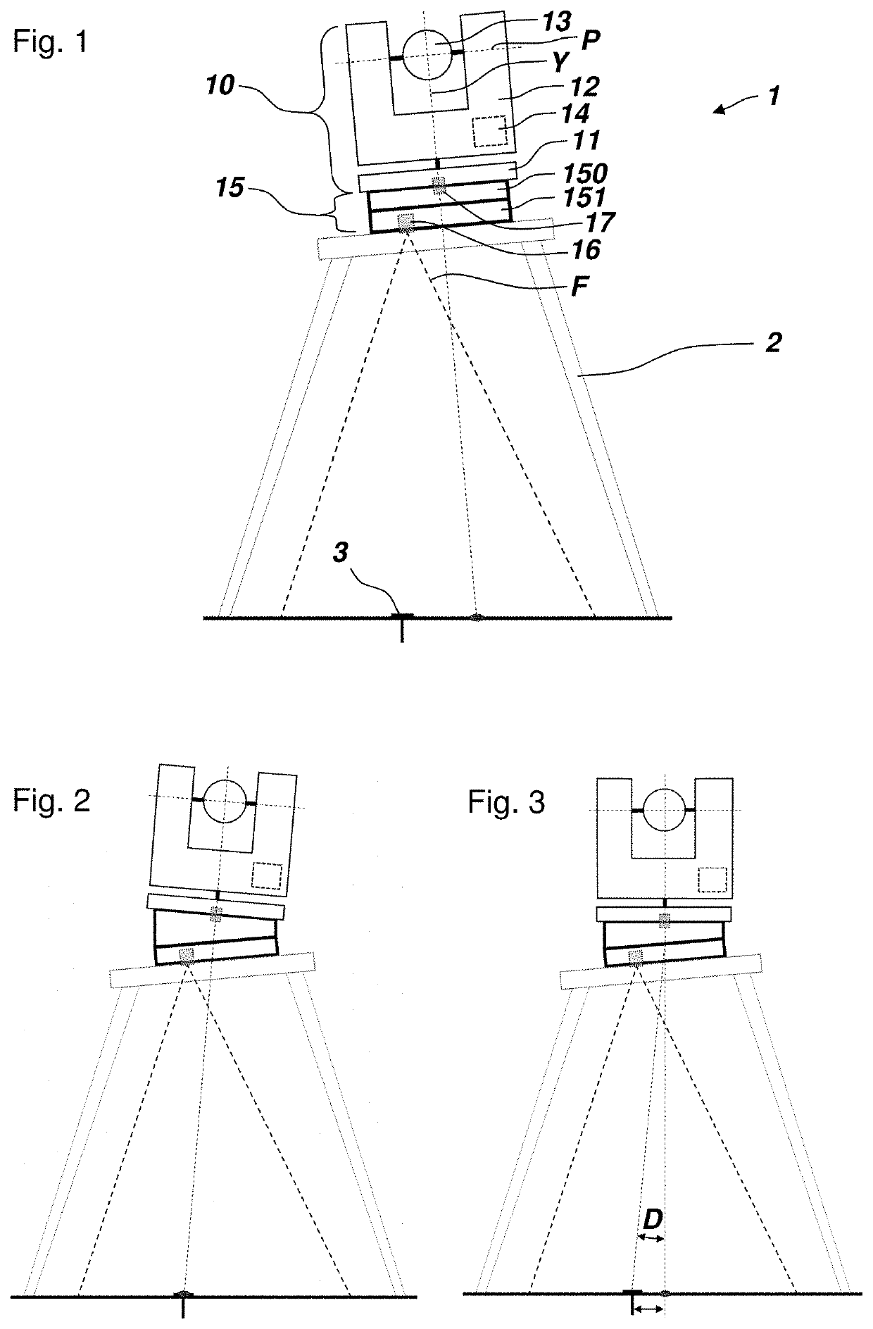
[0029]FIG. 1 shows a surveying system 1 comprising a surveying instrument 10 and a control system (not shown). The control system can be built into or attachable to the surveying instrument 10, outsourced to a remote server, or embodied by an external control device used by the surveyor, e.g. a smart phone or a dedicated surveying controller. Alternatively, the components of the control system can be distributed on two or more of the surveying instrument, the remote server, and the external control device, wherein the components are configured to communicate with each other.

[0030]The surveying instrument 10 is embodied as a total station, however it could in other embodiments be a laser tracker or laser scanner.

[0031]The surveying instrument 10 comprises a base unit 11 configured for positioning the surveying instrument, a support unit 12 mounted on the base unit and configured for being rotatable relative to the base unit around a yaw axis Y (also referred to as standing axis), a t...


PUM


Abstract

A surveying system can include a surveying instrument, a control system, a tilt measuring system, a levelling unit, a camera system, and a second distance meter, wherein the control system is configured for obtaining an image position of a captured image, adjusting a tilt status until a first tilt status is obtained, the second distance meter aiming onto the location on the ground in the first tilt status, determining the first tilt status, effecting the second distance meter to measure a distance to the location on the ground, effecting a first angle encoder to measure a rotatory position of a support unit, effecting the levelling unit to adjust the tilt status, and calibrating a preconfigured centre point based on the distance to the location on the ground, a deviation between the first tilt status and the second tilt status, and/or the rotatory position of the support unit.

Description

CROSS-REFERENCE TO RELATED APPLICATIONS[0001]This application claims priority to European Patent Application No. 19162046.7 filed on Mar. 11, 2019, which is incorporated herein by reference.FIELD OF THE INVENTION[0002]The present invention relates to a surveying system comprising a surveying instrument and a control system. Generic surveying instruments are e.g. total stations, laser scanner, or laser trackers and pertain to the fields of geodesy and / or metrology.BACKGROUND OF THE INVENTION[0003]Surveying instruments are normally set up in a given (local or global) coordinate reference frame. To use standard setup and orientation methods, it is a common procedure to set up the surveying instrument directly over a discrete ground point with known or unknown coordinates using e.g. a tripod.[0004]This procedure usually required three manual steps. At first, the surveying instrument is precisely centred above the ground point. This is usually done with the help of a laser plummet, an op...

Claims


Application Information

Patent Timeline
IPC IPC(8): G01C15/00G01C25/00
CPCG01C25/005G01C15/008G01C15/08G01C15/00G01C1/04
Inventor BERNHARD, HEINZMAAR, HANNESTSYMBAL, DIMITRIGRABHERR, BENJAMIN
Owner LEICA GEOSYSTEMS AG
Why Eureka
Try Eureka