Methods and systems for an integrated charging system for an electric vehicle

Active Publication Date: 2020-09-24
INVERTEDPOWER PTY LTD
View PDF0 Cites 43 Cited by
  • Summary
  • Abstract
  • Description
  • Claims
  • Application Information

AI Technical Summary

Benefits of technology

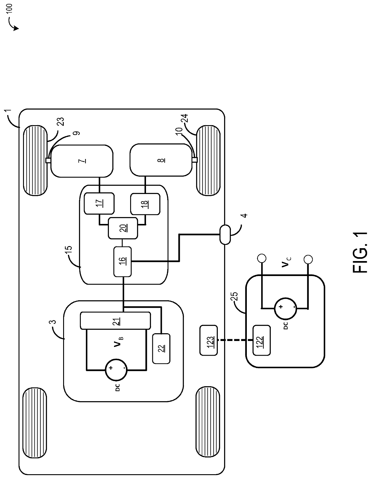
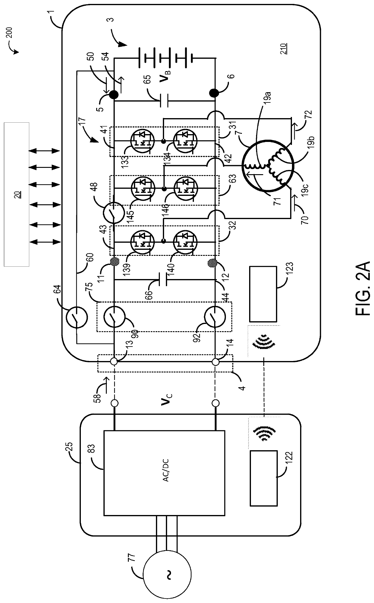
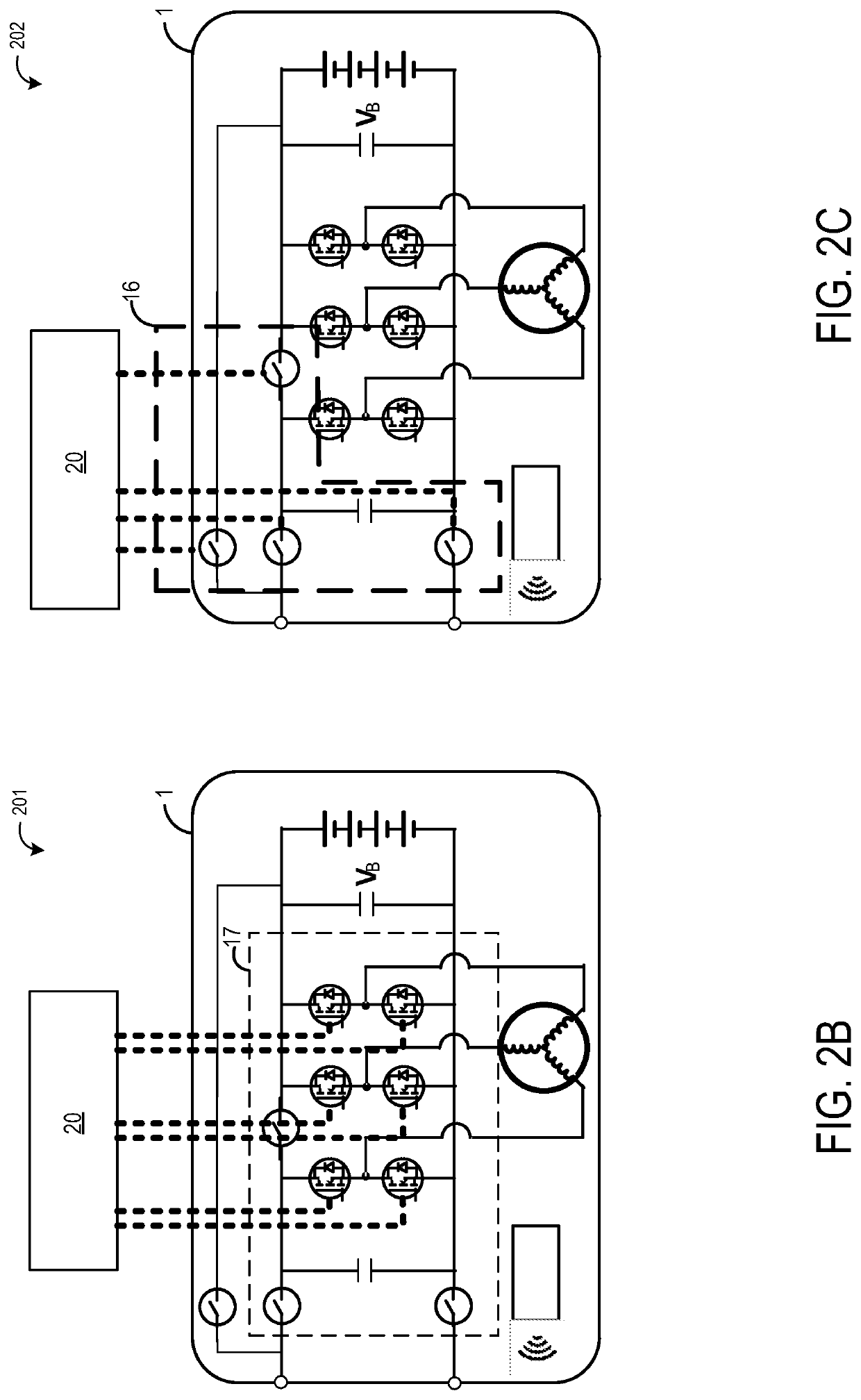
[0007]In an embodiment, the present disclosure provides for a method for a controller for an electric vehicle comprising a first DC energy storage device at a device voltage, a charging interface for interfacing with an external DC source of an external DC voltage, an electric machine including one or more inductive windings, a converter comprising at least two or more drive circuits operating in a first and in a second state, a first DC input and a second DC input to the converter, and a switching mechanism for selectively operating in a first state and in a second state operated by the controller, wherein in the first state the converter is responsive to drawing a drive current from the first DC energy storage device and applying current to at least one of the one or more inductive windings for movi

Problems solved by technology

While improvements to EV design and performance have led to increased demand, the combination of the short ranges available between recharging and long charging times remains a major relative disadvantage in comparison with vehicles with internal combustion engines (ICEs).
By incorporating more efficient batteries that charge up faster and hold charges for longer, successive generations of EVs have increased ranges and shortened charging times. However, this has led to compatibility issues with respect to charging stations.
As a result, newer EVs built for greater recharging voltages and DC power may not be able to recharge at older charging stations.
On the other hand, older EVs with low-power AC recharging circuitry (e.g., designed for plugging into a standard outlet) may not be able to handle the increased voltage and DC power of newer charging stations.
The inventors herein have recognized that the various known arrangements and apparatus for charging electric vehicles may not provide a satisfactory solution to the above mentioned version compatibility problems.
Further, compatibility problems are exacerbated

Method used


Image

  • Methods and systems for an integrated charging system for an electric vehicle
  • Methods and systems for an integrated charging system for an electric vehicle
  • Methods and systems for an integrated charging system for an electric vehicle

Examples


Example

[0027]It is known that consumers favor electric vehicles with longer ranges and faster charge times, and these factors are therefore a significant factor for mass market adoption of these vehicles. Moreover, recent significant reductions in battery costs have enabled a new generation of electric vehicles to emerge with extended ranges, which is achieved due to a significant increase in the available energy storage on board each vehicle. While this may have ameliorated the range concerns of electric vehicles, this extra onboard energy storage takes longer to fully charge. Accordingly, to alleviate the faster charge time requirements, there is a need for a greatly increased power transfer to the onboard storage (e.g., the battery).

[0028]In an attempt to address this need for higher power charge rates, vehicle manufacturers have moved to higher voltages to be able to transfer the power required between the infrastructure (e.g., the charging station) and the vehicle. This solution also ...


PUM


Abstract

Methods and systems are provided for an onboard charging system of an electric vehicle. In one example, the charging system includes a controller for an electric vehicle comprising a first DC energy storage device at a device voltage, a charging interface for interfacing with an external DC source of an external DC voltage, an electric machine including one or more inductive windings, a converter comprising at least two or more drive circuits operating in a first and in a second state, a first DC input and a second DC input to the converter, and a switching mechanism for selectively operating in a first state and in a second state operated by the controller, wherein in the first state the converter is responsive to drawing a drive current from the first DC energy storage device and applying current to at least one of the one or more inductive windings for moving the vehicle, and in the second state, the converter is responsive to drawing a load current from the charging interface and applying an energizing current to at least one of the one or more inductive windings for generating at least one of a regulated charging voltage for the DC energy storage device.

Description

CROSS-REFERENCE TO RELATED APPLICATIONS[0001]The present application is a continuation-in-part of U.S. patent application Ser. No. 15 / 758,694, entitled “CONTROLLER FOR AN INDUCTIVE LOAD HAVING ONE OR MORE INDUCTIVE WINDINGS”, and filed on Mar. 8, 2018. U.S. patent application Ser. No. 15 / 758,694 is a U.S. National Phase of International Application No. PCT / AU2016 / 050852, entitled “A CONTROLLER FOR AN INDUCTIVE LOAD HAVING ONE OR MORE INDUCTIVE WINDINGS”, and filed on Sep. 12, 2016. International Application No. PCT / AU2016 / 050852 claims priority to Australian Application No. 2015903706, filed on Sep. 11, 2015. The present application is also a continuation-in-part of U.S. patent application Ser. No. 16 / 612,354, entitled “A VEHICLE CHARGING STATION”, and filed on Nov. 8, 2019. U.S. patent application Ser. No. 16 / 612,354 is a U.S. National Phase of International Application No. PCT / AU2018 / 000065, entitled “A VEHICLE CHARGING STATION”, and filed on May 8, 2018. International Application...

Claims


Application Information

Patent Timeline
IPC IPC(8): B60L53/60H02P27/08H02J7/34H02J7/02B60L53/53B60L53/66
CPCB60K6/28H02J7/02B60Y2200/91B60L53/66B60L2210/30H02P27/08B60L53/60B60Y2300/91B60Y2200/92B60L53/53H02J7/345B60L53/24H02J7/00034H02J2310/48H02J2207/40Y02T10/64Y02T10/70Y02T10/7072Y02T90/12Y02T90/14Y02T90/16
Inventor SMOLENAERS, STEFAN
Owner INVERTEDPOWER PTY LTD
Why Eureka
Try Eureka