Multi-channel optical fiber rotary junction

Active Publication Date: 2020-09-24
CANON USA +1
View PDF0 Cites 1 Cited by
  • Summary
  • Abstract
  • Description
  • Claims
  • Application Information

AI Technical Summary

Benefits of technology

[0009]The rotary junction as described herein is particularly advantageous since the optical crosstalk, such as th

Problems solved by technology

In reality, coupling efficiency between fibers is not 100%, especially in the case that the fibers are single-mode fibers.
If there is non-negligible optical crosstalk between the fibers in t

Method used


Image

  • Multi-channel optical fiber rotary junction
  • Multi-channel optical fiber rotary junction
  • Multi-channel optical fiber rotary junction

Examples


Embodiment Construction

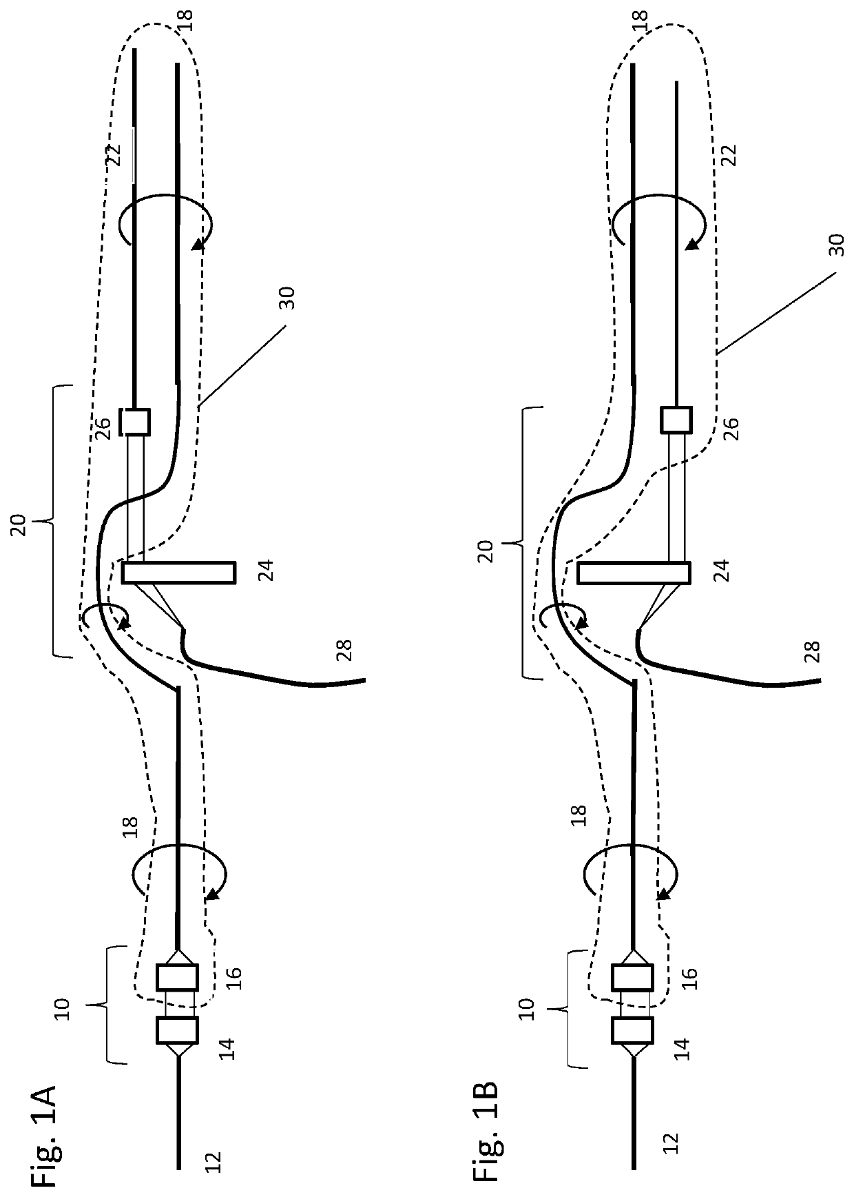
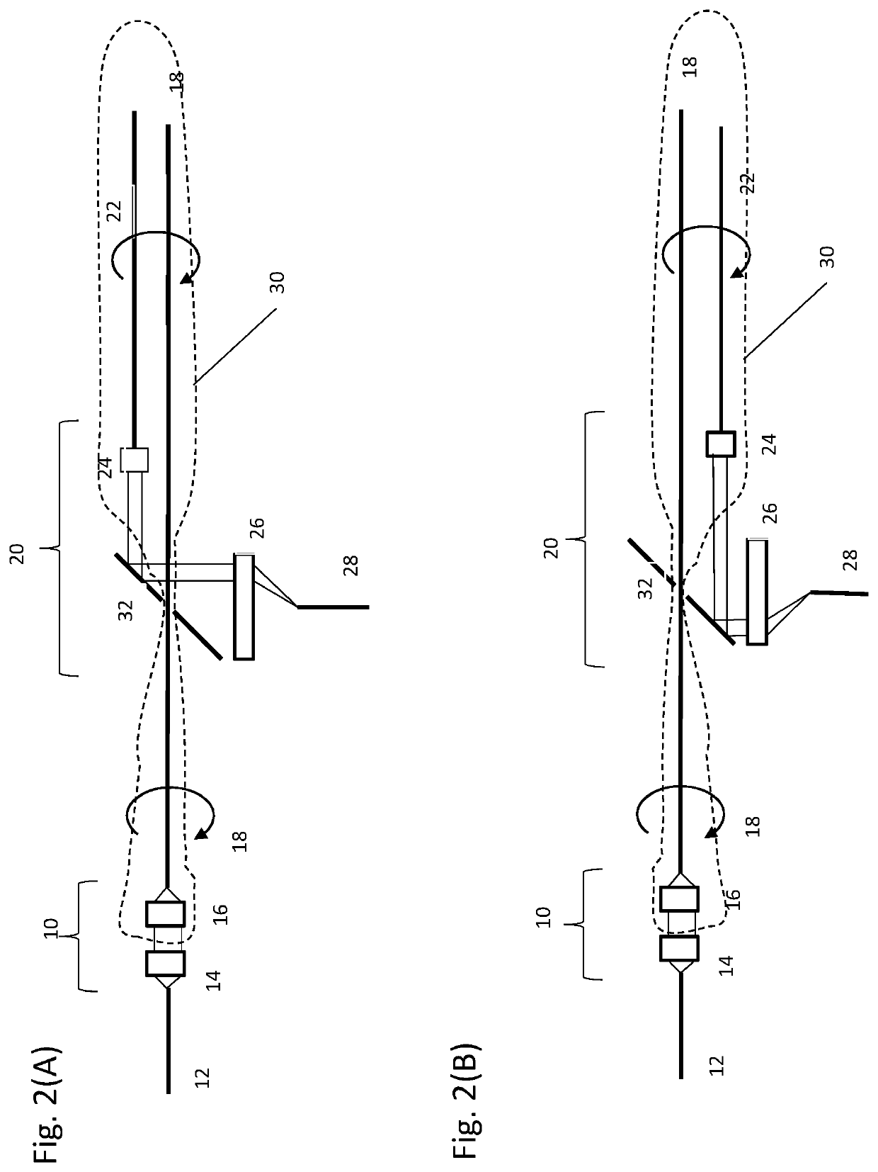
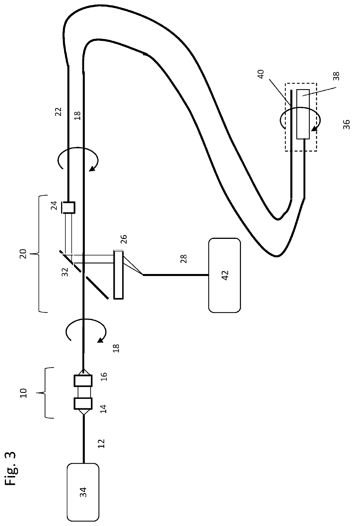
[0008]According to at least one embodiment of the invention, there is provided a rotary junction comprising: a first coupling optic that comprises a first rotor having a stationary side and a rotating side, a first waveguide on a stationary side of the first rotor and, a second waveguide on the rotating side of the first rotor. The rotary junction also has a second coupling optic that comprises a second rotor having a stationary side and a rotating side, a third waveguide on a stationary side of the second rotor and, a fourth waveguide on the rotating side of the second rotor. The second fiber passes through the second coupling optics. In some embodiments, the some or all of the waveguides are optical fibers, such as single mode fibers and / or multi-mode fibers.

[0009]The rotary junction as described herein is particularly advantageous since the optical crosstalk, such as the crosstalk between the second and fourth fiber is low. For example, the optical crosstalk may be less than −60 ...


PUM


Abstract

Exemplary apparatus, systems, methods of making, and methods of using a rotary junction are provided. A rotary junction having multiple channels is provided herein. The rotary junction has a first coupling optic and a second coupling optic where the rotating optical fiber or other waveguide comping from the first coupling optic passes through the second coupling optics.

Description

CROSS-REFERENCE TO RELATED APPLICATION(S)[0001]This application claims priority to U.S. Provisional Application Ser. No. 62 / 312,855 filed 24 Mar. 2016, the content of which is incorporated herein by reference in its entirety.FIELD OF THE DISCLOSURE[0002]The present disclosure relates generally to optical imaging and more particularly to optical rotary junction devices, exemplary apparatus and methods which use the rotary junction for imaging. More particularly, the disclosure exemplifies multi-channel rotary junctions.BACKGROUND INFORMATION[0003]Optical fiber rotary junctions are known for transmission of optical signals between fibers that are rotatable relative to each other. This allows, for example, a stationary light source and detection system combined with a rotating sampling probe. Some applications need two or multiple channel rotary junction. For example, one channel is needed for one type of incident radiation and a second channel is needed for a second type of incident r...

Claims


Application Information

Patent Timeline
IPC IPC(8): G02B6/36G02B6/32G02B23/24
CPCG02B6/32G02B6/3604G02B23/2407
Inventor IKUTA, MITSUHIROKANG, DONGKYUNTEARNEY, GUILLERMO J.
Owner CANON USA
Why Eureka
Try Eureka