Washing machine and method for controlling same

a technology of washing machine and water pump, which is applied in the field of washing machines, can solve the problems of inability to measure the drainage time, abnormal vibration, and significant movement of tubs, and achieve the effect of preventing the occurrence of abnormal vibrations

Active Publication Date: 2020-10-01
SAMSUNG ELECTRONICS CO LTD
View PDF0 Cites 3 Cited by
  • Summary
  • Abstract
  • Description
  • Claims
  • Application Information

AI Technical Summary

Benefits of technology

[0045]The pulsator may be rotated at or above the certain rotation number during the washing operation or the rinsing operation, and the prelude of abnormal vibration may be detected by the vibration sensor during the spin-drying operation. Accordingly, even when the water contained in the waterproof clothes is not completely removed by only rotating the pulsator at high speed, the occurrence of abnormal vibrations may be prevented by adequately controlling the operation of the driving portion according to a detection result of the vibration sensor.
[0046]According to a washing machine and a method of controlling the same, it may be adequately determined on the basis of a water level change rate during a water supply operation or a drainage operation whether a prelude to abnormal vibrations is present. Also, when it is determined that waterproof clothes are accommodated in a drum and the prelude to abnormal vibrations is present, occurrence of abnormal vibrations may be prevented during a spin-drying operation by adequately controlling an operation of a driving portion.

Problems solved by technology

However, when laundry having a waterproofing property such as waterproof bedding, a nylon cover, a raincoat, or the like is included, water remains in waterproof laundry or the waterproof laundry is attached to the inner circumferential surface of the drum and obstructs dehydrating holes during the washing operation or the rinsing operation such that the water may not completely drain during the drainage operation.
When the spin-drying operation is started in this state and a rotating speed of the drum reaches 1000 revolutions per minute (rpm) or more, the water which remains in the waterproof laundry moves such that abnormal vibrations occur and the tub rocks and moves significantly.
However, it is impossible by only measuring a drainage time like the inventions of Patent Documents 1 and 2 to accurately determine whether waterproof clothes are present.
Meanwhile, since drainage is not easily performed when waterproof clothes partially obstruct dehydrating holes, a drainage time is increased by as much as the waterproof clothes obstruct the dehydrating holes.
However, for example, when the water supply operation is temporarily stopped, the water level change rate may not be precisely calculated.

Method used


Image

  • Washing machine and method for controlling same
  • Washing machine and method for controlling same
  • Washing machine and method for controlling same

Examples


first embodiment

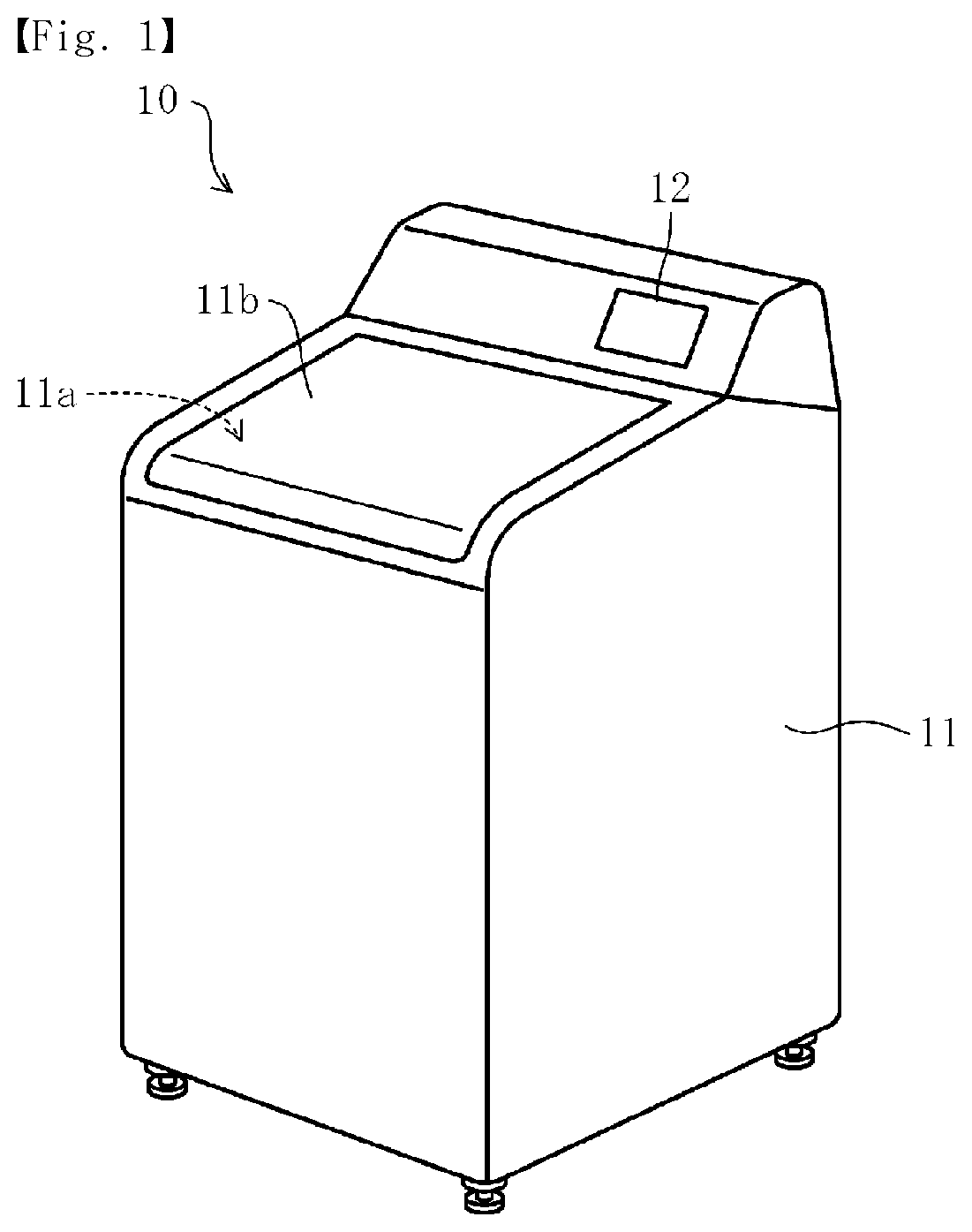
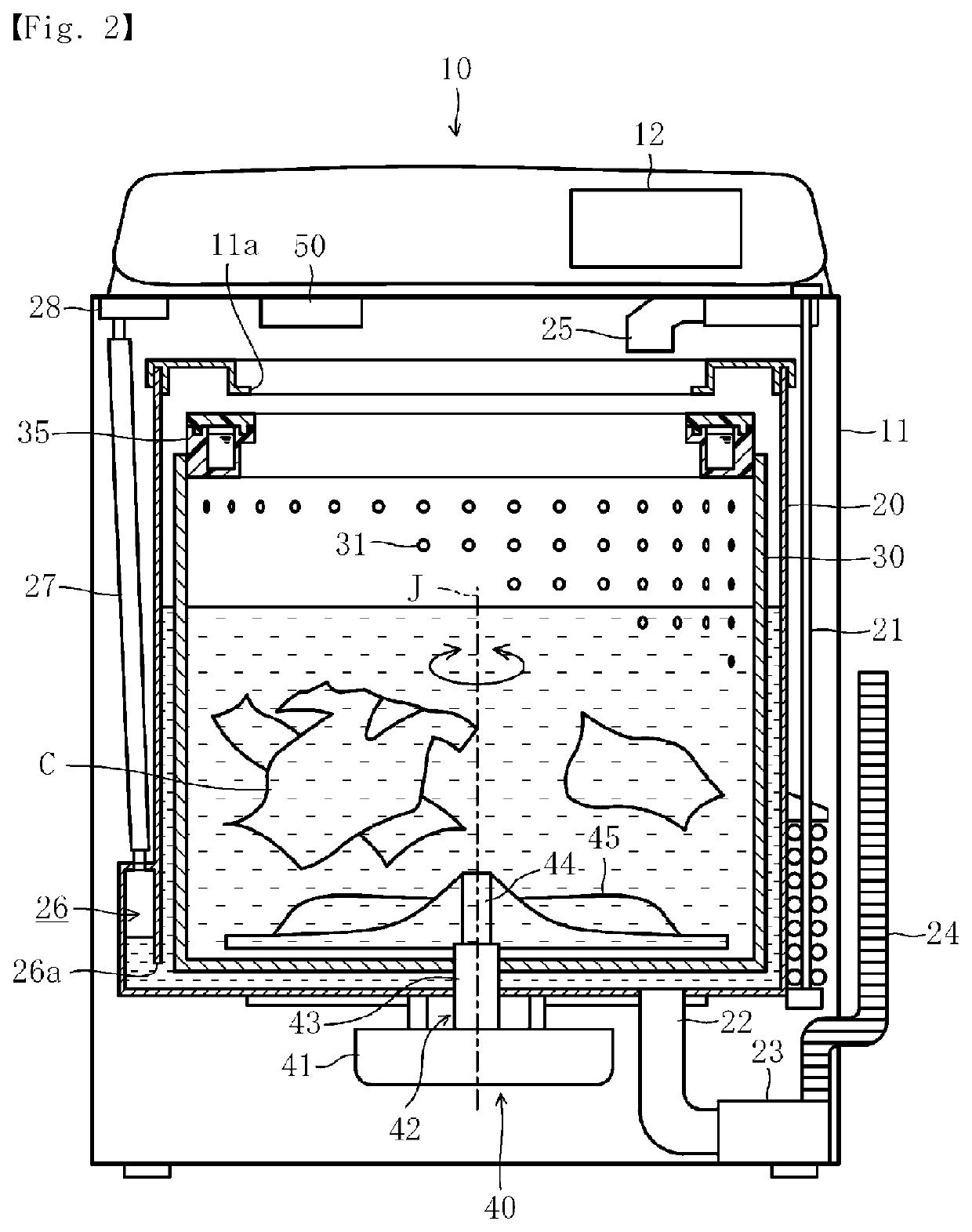
[0061]FIG. 1 is a perspective view illustrating the entire configuration of a washing machine according to Embodiment 1 of the present invention, and FIG. 2 is a longitudinal cross-sectional view illustrating the entire configuration of the washing machine.

[0062]In FIGS. 1 and 2, a washing machine 10 according to an embodiment of the present invention includes a rectangular box-shaped case 11. An operation portion 12 for allowing a user to operate the washing machine is formed at a top of the case 11. The operation portion 12 includes an operation switch 13, a display panel 14, and a light emitting diode (LED) 15 (refer to FIG. 3). The washing machine 10 may automatically perform each of “water supplying,”“washing,”, “rinsing,” and “spin-drying” in a row by operating the operation switch 13.

[0063]In the case 11, an outer water tub (hereinafter, referred to as “a tub”) 20, an inner water tub (hereinafter, referred to as “a drum”) 30, a driving device 40, a pulsator 45, a balancer 35,...

embodiment 2

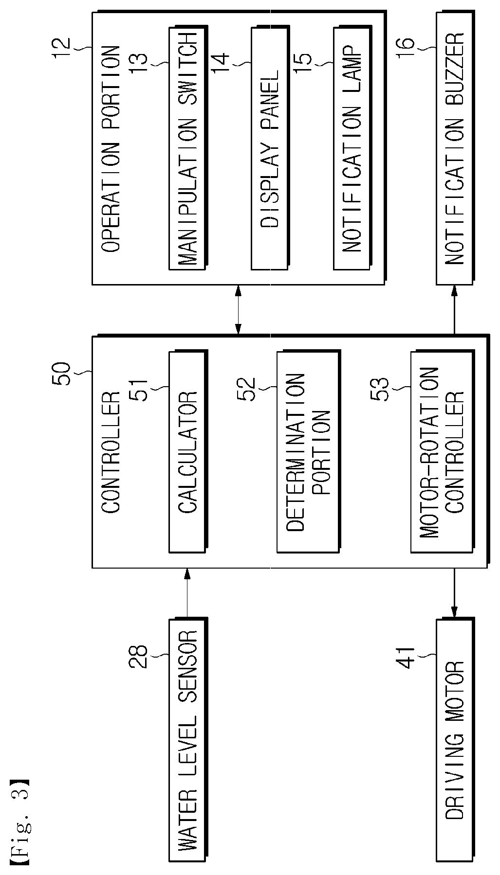
[0117]FIG. 8 is a block diagram illustrating a control operation of a washing machine according to Embodiment 2 of the present invention. Here, portions like those in Embodiment 1 will be referred to with like reference numerals and only differences therebetween will be described.

[0118]In FIG. 8, in addition to the driving motor 41, the water level sensor 28, the operation portion 12, and the notification buzzer 16, a vibration sensor 36, an opening or closing sensor (an opening or closing detector) 37, and a communication portion (a notification portion) 38 are connected to the controller 50.

[0119]The vibration sensor 36 is installed at the tub 20 of the washing machine 10 and detects vibration of the tub 20.

[0120]The opening or closing sensor 37 detects an opened or closed state of the cover 11b and is configured as a proximity sensor or a magnetic sensor. The opening or closing sensor 37 is installed at a circumferential edge portion of the inlet 11a of the case 11. A permanent m...

embodiment 3

[0152]FIG. 11 is a side cross-sectional view illustrating a configuration of a driving motor mounted on a washing machine according to Embodiment 3 of the present invention.

[0153]In the washing machine 10 according to Embodiment 3, the driving motor 41 is configured to be a so-called dual-rotor motor to drive the drum 30 and the pulsator 45 to independently rotate.

[0154]In FIG. 11, the driving motor 41 includes an outer rotor (a second rotor) 46, an inner rotor (a first rotor) 47, an inner shaft (a first rotating shaft) 43, an outer shaft (a second rotating shaft) 44, a ring-shaped stator 48, and the like. That is, the driving motor 41 is a so-called dual-rotor motor which includes the outer rotor 46 and the inner rotor 47 in a radially outward direction and a radially inward direction of one stator 48.

[0155]Also, since the outer rotor 46 and the inner rotor 47 are connected to the pulsator 45 or the drum 30 not through a clutch, an accelerator / decelerator, or the like, the driving ...


PUM


Abstract

According to the present invention, it is appropriately determined whether there is a portent of abnormal vibration or not, and an appropriate control is conducted such that no abnormal vibration occurs during a dewatering stroke. A control unit comprises a calculation unit, a determination unit, and a motor rotation control unit. The calculation unit calculates the rate of change in water level, which indicates the amount of change in water level per a predetermined period of time, on the basis of the result of sensing by a water level sensor in connection with a water supply stroke. The determination unit determines whether laundry having a waterproof property is contained in a drum or not on the basis of the rate of change in water level during the water supply stroke calculated by the calculation unit. When it is determined that laundry having a waterproof property is contained in the drum, the motor rotation control unit controls the operation of a driving motor such that the drum is rotated at a predetermined number of rotations or less during the dewatering stroke.

Description

CROSS-REFERENCE TO RELATED APPLICATIONS[0001]This application is a 371 of International Application No. PCT / KR2016 / 015021 filed on Dec. 21, 2016, which claims priority to Japanese Patent Application No. 2015-255273 filed on Dec. 25, 2015, Japanese Patent Application No. 2016-059468 filed on Mar. 24, 2016, and Japanese Patent Application No. 2016-226899 filed on Nov. 22, 2016, the disclosures of which are herein incorporated by reference in their entirety.BACKGROUND1. Field[0002]The present invention relates to a washing machine which controls such that abnormal vibrations do not occur during a spin-drying operation and a method of controlling the same.2. Description of Related Art[0003]Generally, a washing machine (for example, a fully automatic washing machine) is an apparatus which includes an outer tub (hereinafter, referred to as ‘a tub’) for storing water (wash water or rinse water), a washing and spin-drying tub (hereinafter, referred to as ‘a drum’) which is rotatably install...

Claims


Application Information

Patent Timeline
Patent Type & Authority Applications(United States)
IPC IPC(8): D06F33/00D06F37/30D06F33/47
CPCD06F37/24D06F39/083D06F39/088D06F37/304D06F39/087D06F33/00D06F33/47D06F33/48D06F2103/18D06F2103/26D06F2105/46D06F33/42D06F33/34D06F34/05D06F34/16D06F34/28D06F37/40D06F2103/40D06F2105/62D06F39/08
Inventor OHYAGI, ATSUSHISHINOHARA, NOBUHIKOKIM, MINSUTAKITA, HIROKI
Owner SAMSUNG ELECTRONICS CO LTD
Why Eureka
Try Eureka