Brake system and fluid pressure motor including the same
- Summary
- Abstract
- Description
- Claims
- Application Information
AI Technical Summary
Benefits of technology
Problems solved by technology
Method used
Image

Examples
first embodiment
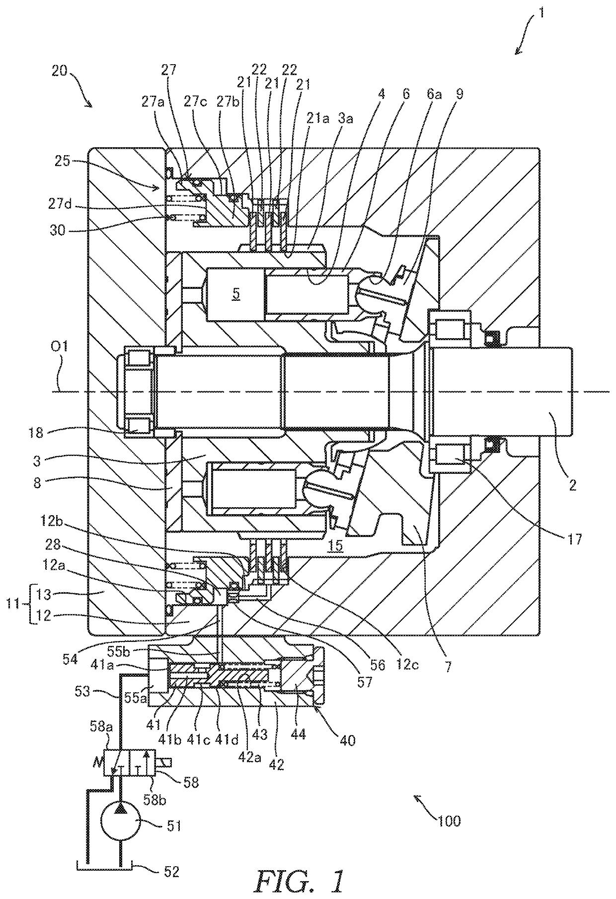
[0012]With reference to FIG. 1, a brake system 100 serving as an embodiment of the present invention will be described. FIG. 1 is a sectional view showing the entire configuration of a hydraulic motor 1 serving as a fluid pressure motor to which the brake system 100 is applied.
[0013]First, the entire configuration of the hydraulic motor 1 will be described with reference to FIG. 1. The hydraulic motor 1 is, for example, a swash plate type hydraulic motor used for a traveling device or a turning device of a construction machine, etc.
[0014]The hydraulic motor 1 includes an output shaft 2 coupled to a driven body (not shown) serving as a load, and a cylinder block 3 coupled to the output shaft 2 which is configured to be rotated integrally with the output shaft 2. The output shaft 2 is rotatably supported by a case 11 via two bearings 17, 18. The case 11 is divided into a housing case 12 configured to house the cylinder block 3, and a lid member 13 combined with the housing case 12 via...
second embodiment
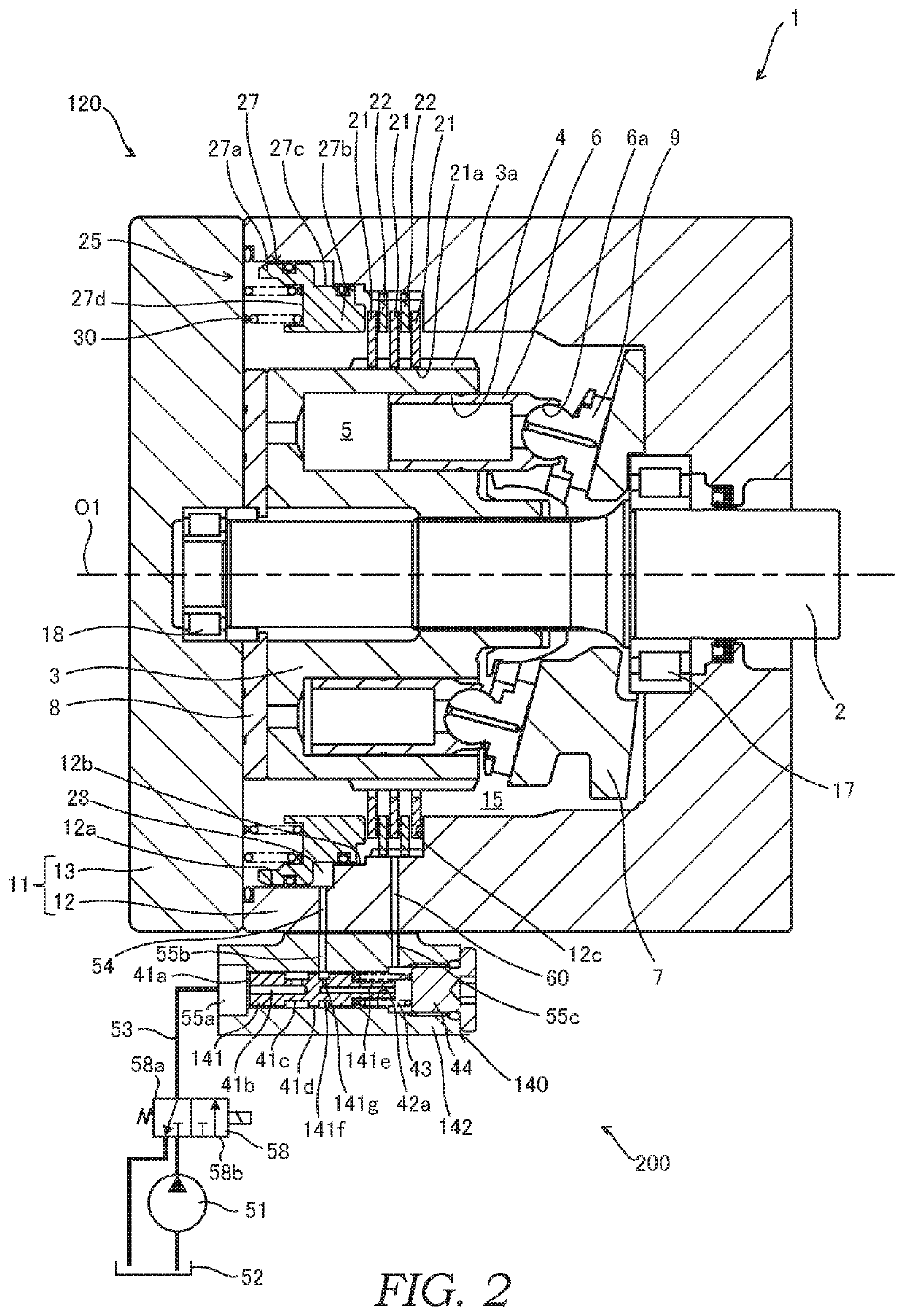
[0068]Next, with reference to FIG. 2, a brake system 200 according to a second embodiment of the present invention will be described. Hereinafter, different points from the first embodiment will be mainly described, and the same configurations as the first embodiment will be given the same reference signs and description thereof will be omitted.
[0069]The basic configurations of the brake system 200 are the same as those of the brake system 100 according to the first embodiment. The brake system 200 is different from the brake system 100 in a point that working oil in a brake cancellation chamber 28 is discharged through a valve device 140.
[0070]The brake system 200 includes a brake device 120 configured to cancel brake force by supply of pressurized working oil and generate the brake force by discharge of the working oil, supply passages 53, 54 through which the working oil pressurized in a hydraulic pump 51 is supplied to the brake device 120, the valve device 140 provided in the s...
third embodiment
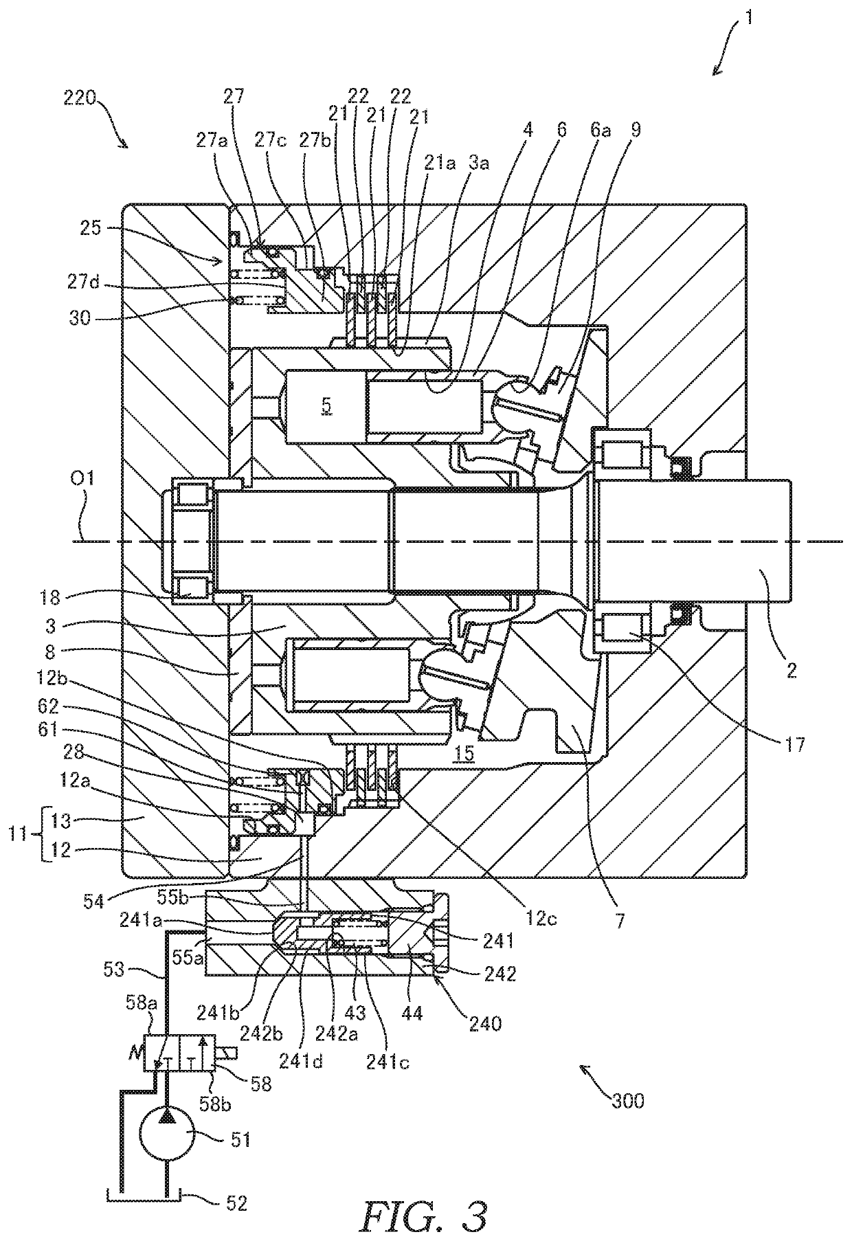
[0093]Next, with reference to FIG. 3, a brake system 300 according to a third embodiment of the present invention will be described. Hereinafter, different points from the first embodiment will be mainly described, and the same configurations as the first embodiment will be given the same reference signs and description thereof will be omitted.
[0094]The basic configurations of the brake system 300 are the same as those of the brake system 100 according to the first embodiment. The brake system 300 is different from the brake system 100 in a point that a valve element of a valve device 240 is a poppet valve 241 and a point that a discharge passage 61 is formed in a brake piston 27.
[0095]The brake system 300 includes a brake device 220 configured to cancel brake force by supply of pressurized working oil and generate the brake force by discharge of the working oil, supply passages 53, 54 through which the working oil pressurized in a hydraulic pump 51 is supplied to the brake device 2...
PUM
 Abstract
Description
Claims
Application Information
 - Generate Ideas
- Intellectual Property
- Life Sciences
- Materials
- Tech Scout
- Unparalleled Data Quality
- Higher Quality Content
- 60% Fewer Hallucinations
Browse by: Latest US Patents, China's latest patents, Technical Efficacy Thesaurus, Application Domain, Technology Topic, Popular Technical Reports.
© 2025 PatSnap. All rights reserved.Legal|Privacy policy|Modern Slavery Act Transparency Statement|Sitemap|About US| Contact US: help@patsnap.com