
Device For Determining The Anteversion Angle

Active Publication Date: 2020-10-15
STRYKER EURO OPERATIONS HLDG LLC
View PDF0 Cites 0 Cited by
  • Summary
  • Abstract
  • Description
  • Claims
  • Application Information

AI Technical Summary

Benefits of technology

The invention provides a device, system, and method for determining the angle of the femoral shaft of a femur. The device automatically identifies landmarks on the femur and calculates the angle based on the distance between the landmarks in image data. This reduces the amount of radiation to which the patient is exposed and allows for a more efficient evaluation of the angle. The device can also acquire additional images to improve accuracy and minimize errors. Overall, the invention provides a more efficient and accurate way to evaluate the angle of the femoral shaft.

Problems solved by technology

In every surgery, where intraoperative imaging is used, it is a challenge to accurately perform the necessary steps of a procedure of treating a bone fracture.

Method used


Image

  • Device For Determining The Anteversion Angle
  • Device For Determining The Anteversion Angle
  • Device For Determining The Anteversion Angle

Examples


Embodiment Construction

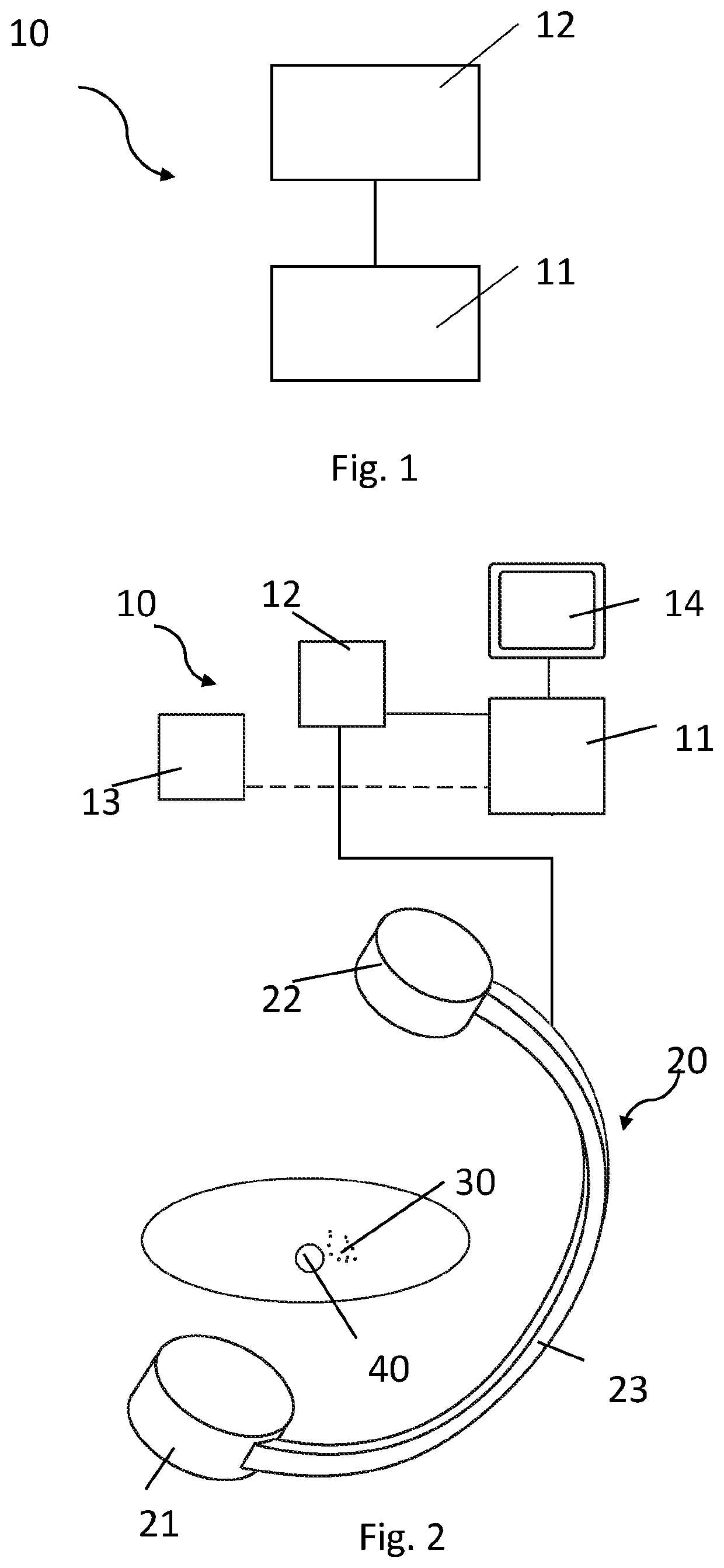
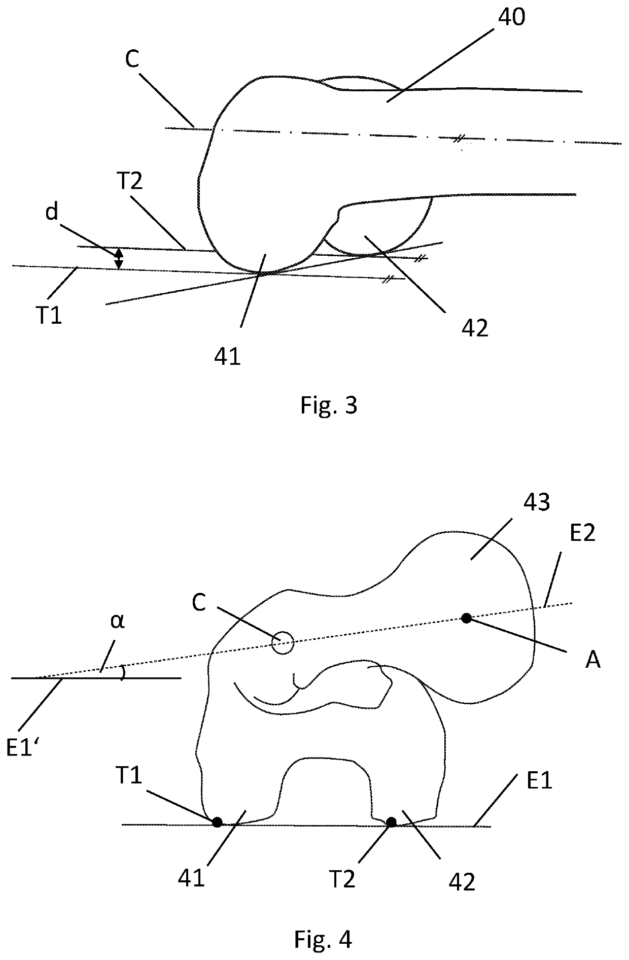
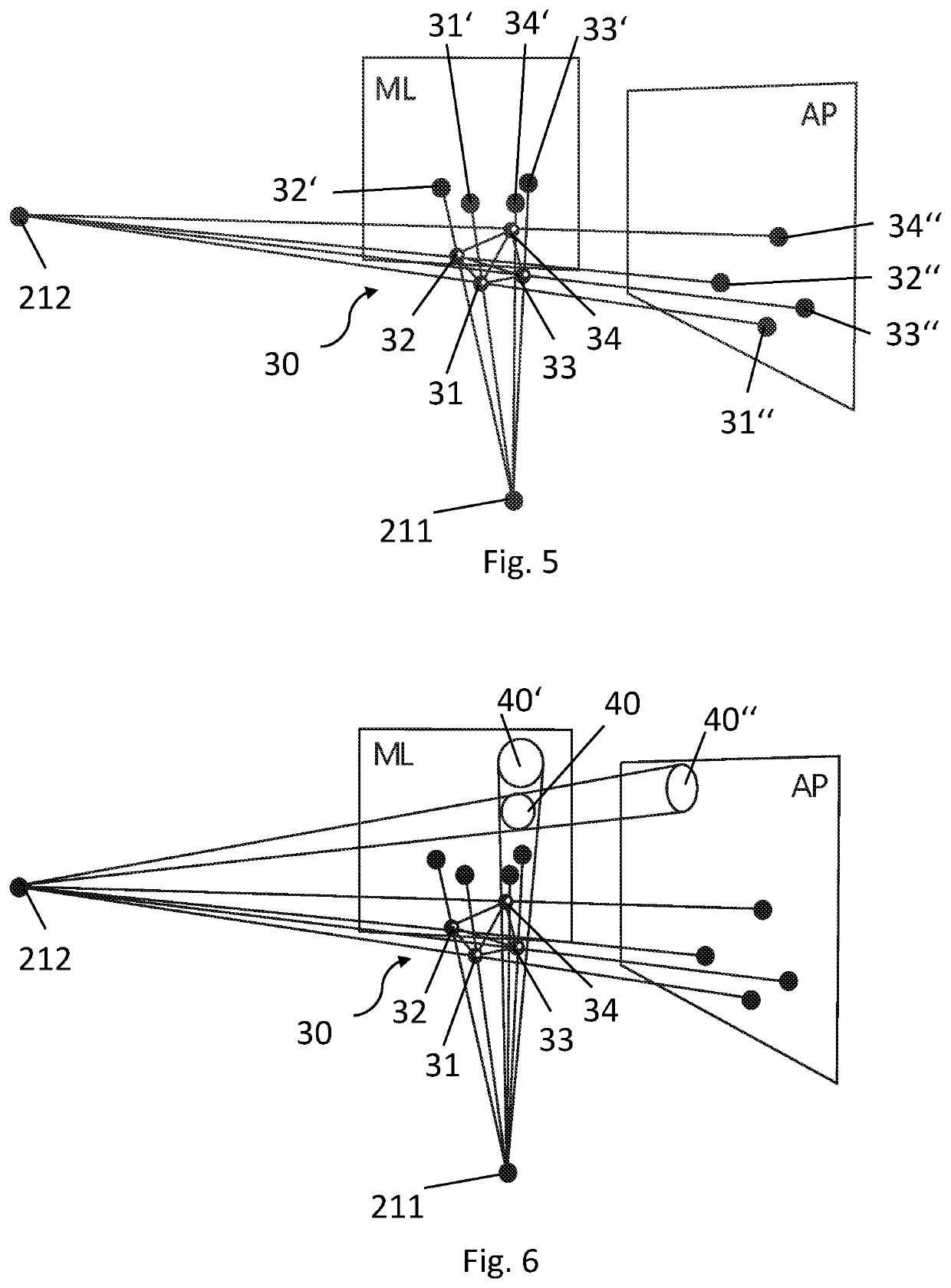
[0053]FIG. 1 illustrates an exemplary embodiment of a device 10 for determining the anteversion angle of a femoral shaft. The device 10 comprises a processing unit 11 and a provision unit 12. The provision unit 12 is configured to provide image data of the femur of which the anteversion angle should be determined. The processing unit 11 is configured to determine a longitudinal shaft axis through the femoral shaft based on the provided image data of the provision unit 12. The processing unit 11 further is configured to determine at least two landmarks of the femur and to place tangents through each one of the landmarks. The landmarks may be the condyles and / or the lowest point of the condyles. The processing unit 11 may determine the landmarks, e.g. the lowest point of the condyles, the femur head and / or the shaft axis through the femoral shaft, automatically, by the means of image recognition, image processing and / or feature extraction. Thus, the processing unit 11 analyses the pro...


PUM


Abstract

A device, a system and a method for determining an anteversion angle of a femoral shaft of a femur are provided. The device includes a provision unit and a processing unit. The provision unit is configured to provide image data of the femur, and wherein the processing unit is configured to determine a longitudinal shaft axis extending through the femoral shaft based on the image data. The processing unit is further configured to determine at least two landmarks of the femur based on the image data, and place a tangent trough each landmark parallel to the shaft axis. The processing unit is configured to determine the anteversion angle of the femoral shaft based on the tangents and the shaft axis of the femoral shaft.

Description

FIELD OF THE INVENTION[0001]The invention relates to the field of X-ray assistance for surgery. In particular, the invention relates to a device, a system and a method for determining the anteversion angle based on two tangents through two landmarks of the femur.BACKGROUND OF THE INVENTION[0002]In every surgery, where intraoperative imaging is used, it is a challenge to accurately perform the necessary steps of a procedure of treating a bone fracture. Usually, almost each step requires an iterative process based on several X-ray images. A significant radiation exposure is thus produced. The amount of radiation may be highly dependent on the know-how and skill of the physician.[0003]Some systems may provide virtual information about a current position of an implant related to a bone. Also it may be possible to provide information on how to adjust the current implant or instrument position to optimise the current procedural steps. However, the availability of this information is highl...

Claims


Application Information

Patent Timeline
IPC IPC(8): A61B6/00G06T7/60G06T7/73G16H30/40G16H50/30
CPCA61B6/4441G16H30/40G16H50/30G06T7/73G06T2207/10116A61B6/505A61B2090/067G06T2207/30008G06T7/60A61B6/5217A61B17/72A61F2002/4668A61B2090/3764
Inventor BLAU, ARNO
Owner STRYKER EURO OPERATIONS HLDG LLC
Learn More