Systems and methods to reduce scattering in temporal focusing multiphoton microscopy

a multi-photon microscopy and temporal focus technology, applied in the field of multi-photon fluorescence microscopy, can solve the problems of limited imaging speed, slow conventional multi-photon microscopy, and hinder the study of biological fast dynamics, so as to reduce scattering influence, high image acquisition speed, and high acquisition speed

Active Publication Date: 2020-10-29
MASSACHUSETTS INST OF TECH
View PDF1 Cites 8 Cited by
  • Summary
  • Abstract
  • Description
  • Claims
  • Application Information

AI Technical Summary

Benefits of technology

[0004]Systems and methods described herein provide improved imaging of deep tissue samples using line-scanning and wide-field techniques at high acquisition speeds. In various embodiments, the systems and methods employ multiphoton imaging systems and methods including temporal focusing and fluorescence imaging. In some embodiments, the systems and methods enable imaging deep inside scattering tissue at high speeds by line-scanning or projection of structured excitation patterns into a selected depth within the material being imaged and reconstructing an image from information acquired from the detected images to limit the influence of scattering. Advantageously, the present systems and methods can provide line-scanning or wide-field multiphoton microscopy imaging at high image acquisition speeds while maintaining optical sectioning in thick samples.

Problems solved by technology

Despite its utility, however, conventional multiphoton microscopy is slow because the diffraction-limited size of the laser beam that scans over a region of interest.
The imaging speed is limited by the speed of raster scanning due to the signal-to-noise ratio requirements for a single pixel.
This limited imaging speed hinders the study of fast dynamics of biological events, such as neuronal activity, that occur at a faster time scale than the raster rate of the scanning components.
Outside the focal plane, the stretched pulse duration reduces beam intensity, which correspondingly lowers the multiphoton excitation efficiency and results in fewer photons originating from out-of-focus locations.
However, scattered photons can contribute to photons counted in adjacent pixels resulting in degradation of the image.
This degradation limits the use of temporal focusing in deep tissue imaging applications.

Method used


Image

  • Systems and methods to reduce scattering in temporal focusing multiphoton microscopy
  • Systems and methods to reduce scattering in temporal focusing multiphoton microscopy
  • Systems and methods to reduce scattering in temporal focusing multiphoton microscopy

Examples


Embodiment Construction

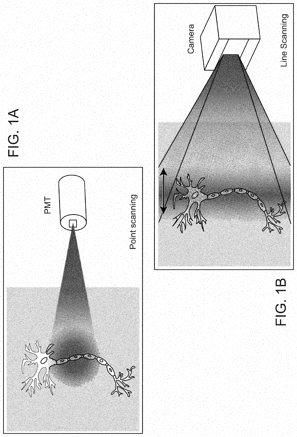
[0048]Systems and methods described herein provide improved multiphoton microscopic imaging methods that overcome limitations due to emission scattering. As compared to conventional point-scanning methods, the systems and methods described herein provide faster data acquisition without sacrificing signal-to-noise ratio in the final image. Systems and methods described herein spatially encode illuminated regions using structured illumination to illuminate a sample and decode spatial information in the sample from the resulting images. In some embodiments described herein, multiline angular scanning temporal focusing (masTF) can be used to increase imaging speed and reduce scattering using photon reassignment techniques. In some embodiments described herein, arbitrary pattern projecting wide-field temporal focusing (APP-WFTF) can be used to encode sections of the thick sample with arbitrary patterns to enable subsequent reconstruction. In some embodiments herein, De-scattering with Ex...


PUM

PropertyMeasurementUnit
thickaaaaaaaaaa
thickaaaaaaaaaa
full-width half-maximumaaaaaaaaaa

Abstract

Systems and methods herein provide improved, high-throughput multiphoton imaging of thick samples with reduced emission scattering. The systems and methods use structured illumination to modify the excitation light. A reconstruction process can be applied to the resulting images to recover image information free of scattering. The disclosed systems and methods provide high throughput, high signal-to-noise ratio, and high resolution images that are depth selective.

Description

CROSS REFERENCE TO RELATED APPLICATIONS[0001]This application is a continuation of International Patent Application No. PCT / US2019 / 015272, filed Jan. 25, 2019, which claims priority to U.S. Provisional Application No. 62 / 622,692, filed Jan. 26, 2018, the entire contents of each application being incorporated herein by reference. This application is also related to U.S. patent application Ser. No. 16 / 258,307, filed Jan. 25, 2019, the entire contents of which is incorporated herein by reference.BACKGROUND OF THE INVENTION[0002]Since its invention, multiphoton fluorescence microscopy has become a standard imaging technique used to study biological systems in part due to its relative simplicity and intrinsic optical sectioning. Examples of multiphoton fluorescence microscopic systems are described in International Patent Publication No. WO 2006 / 127967, filed May 25, 2006 by P. T. C. So et al., the entire content of which is incorporated herein by reference. For a multiphoton fluorescenc...

Claims


Application Information

Patent Timeline
Patent Type & Authority Applications(United States)
IPC IPC(8): G06K9/00G02B21/00G02B21/16G02B21/06A61B1/00G01N21/64
CPCA61B1/00172G02B21/0076G02B21/06G06K9/00127G01N2001/282G02B2207/114G01N21/6458G02B21/16G02B21/0032G02B21/367G06V20/69
Inventor PARK, JONG KANGWADDUWAGE, DUSHANXUE, YINEDIVI, ELLYSO, PETER T.C.ROWLANDS, CHRISTOPHERBERRY, KALEN
Owner MASSACHUSETTS INST OF TECH
Why Eureka
Try Eureka