A power supply controller

a power supply controller and controller technology, applied in the direction of power conversion systems, dc-dc conversion, instruments, etc., can solve problems such as stability trade-offs

Active Publication Date: 2020-11-12
ROHM CO LTD
View PDF8 Cites 2 Cited by
  • Summary
  • Abstract
  • Description
  • Claims
  • Application Information

AI Technical Summary

Problems solved by technology

A known problem with such feedback control systems is that there is a tradeoff in stability in order to allow for improved transient response.

Method used


Image

  • A power supply controller
  • A power supply controller
  • A power supply controller

Examples


Embodiment Construction

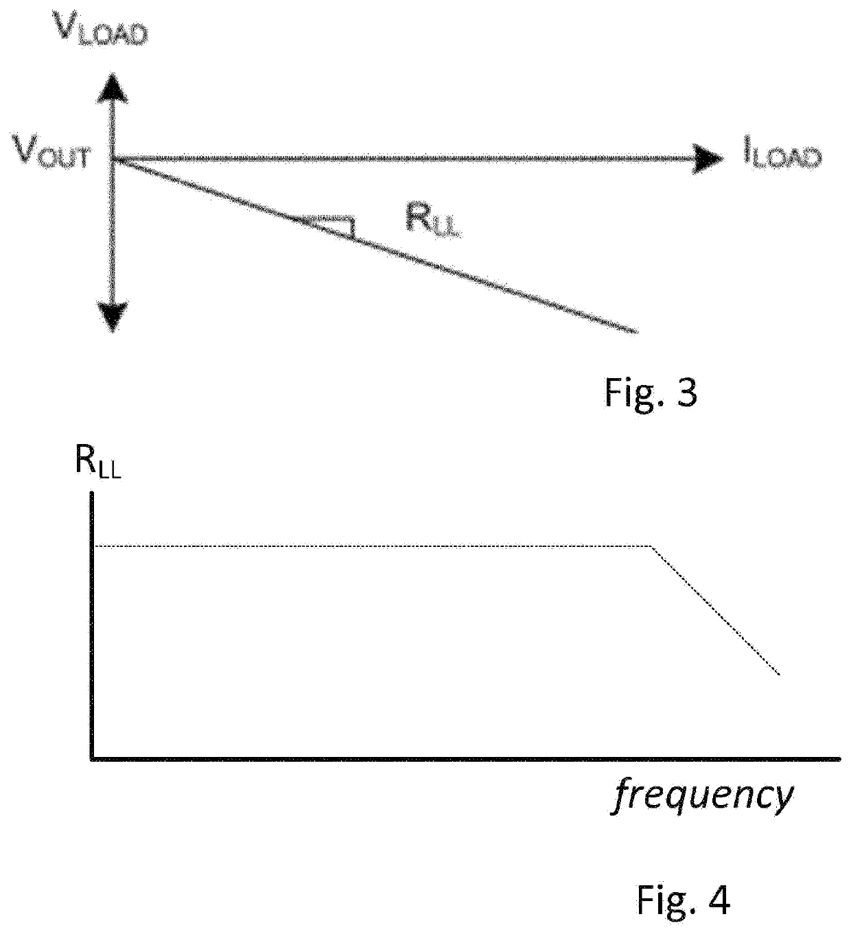
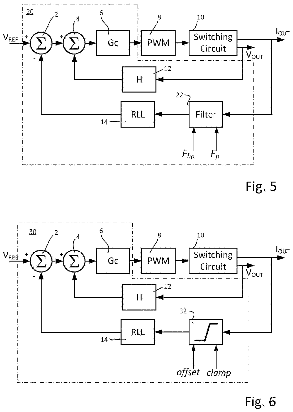
[0035]The present application provides an improved load-line feedforward control arrangement in which constraints are imposed upon the load-line feedforward part of the control arrangement to improve the performance of the control arrangement.

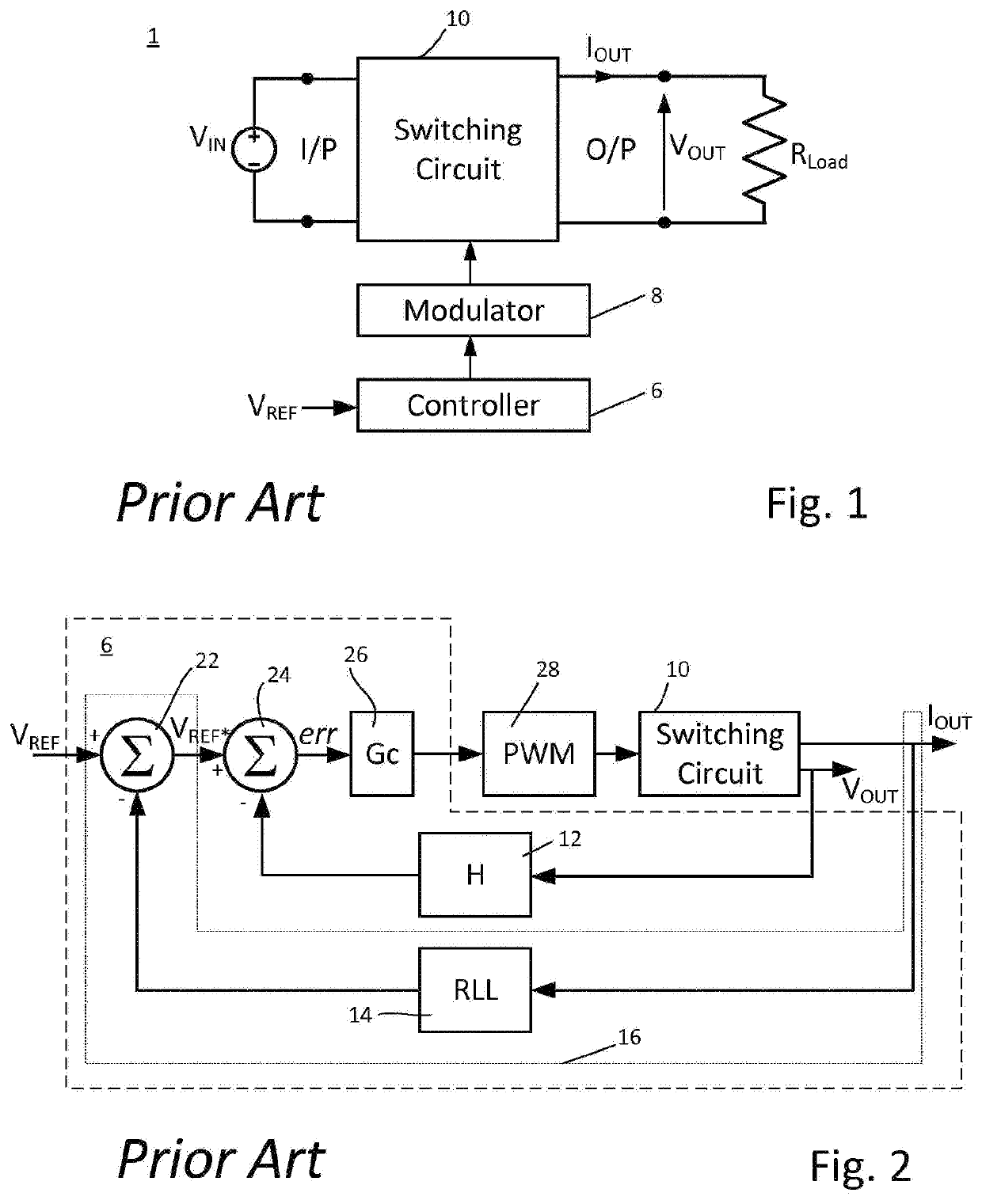
[0036]One place where resistive load line techniques are employed is with current sharing loops. Unfortunately, these loops must be outside the voltage control loops and necessitate that their response BW be significantly lower. Typically, a rule of thumb chosen is that the current sharing loop BW< 1 / 10 voltage loop BW and as a result current sharing loop cannot balance high frequency disturbances such that the outer current sharing loop is too slow to provide adequate current sharing during any event that causes a step (or high frequency) change in the voltage loop error.

[0037]At the same time, when operating multiple voltage mode controllers in parallel, significant voltage error can persist when slewing the references due to small timing err...


PUM


Abstract

The present application provides a controller for a switching power supply such as a DC-DC converter which provides an output voltage and an output current. The controller is configured to provide at least one control signal to operate the switching power supply to maintain the output voltage at a first reference voltage. The controller employs a load line compensator responsive to output current for adjusting the reference voltage employed by the compensator. The load line compensator employs one or either or both of a high pass filter or saturating element to provide a filtered/saturated value which is the value employed in adjusting the reference voltage.

Description

CROSS-REFERENCE TO RELATED APPLICATION[0001]This application is a U.S. National Stage Patent Application filed under 35 U.S.C. § 371 of International Patent Application Number PCT / EP2017 / 069877 filed Aug. 6, 2017, which claims priority under 35 U.S.C. § 119(e) to U.S. Provisional Patent Application No. 62 / 371,502 filed Aug. 5, 2016, the entire contents of all of which are hereby incorporated by reference as if fully set forth herein for all purposes.FIELD OF THE APPLICATION[0002]The present application relates to switching power supplies and in particular to a controller for a switching power supply.BACKGROUND OF THE APPLICATION[0003]The general purpose of a controller in a power supply is to try and ensure that the output voltage of the power supply follows a reference value.[0004]A conventional arrangement employing such a controller is shown generally in FIG. 1.[0005]In the arrangement shown, the power supply circuit has a switching circuit 10 which provides a regulated output vo...

Claims


Application Information

Patent Timeline
Patent Type & Authority Applications(United States)
IPC IPC(8): H02M3/156
CPCH02M2001/0025H02M3/156H02M2001/0016H02M1/0016H02M1/0025
Inventor HARTMAN, MARKCHEN, JINGQUANMINCEY, JEFFREY D.
Owner ROHM CO LTD
Why Eureka
Try Eureka