

Fuel cell separator precursor, and fuel cell separator
a fuel cell separator and precursor technology, applied in the direction of electrochemical generators, sustainable manufacturing/processing, final product manufacturing, etc., can solve the problems of degrading electroconductivity, poor strength of the available separator, and non-uniform distribution of the electroconductive components, so as to improve not only mechanical properties including flexural elasticity, but also the effect of eliminating the dispersion of electroconductivity
- Summary
- Abstract
- Description
- Claims
- Application Information
AI Technical Summary
Benefits of technology
Problems solved by technology
Method used
Image

Examples
manufacturing example 1
[0071]Eighty-four parts by weight of the synthetic graphite, 6 parts by weight of the PAN-based carbon fiber, 5 parts by weight of the cellulose fiber, and 5 parts by weight of the PP fiber were placed in water, and the mixture was stirred to obtain a fiber shiny. The slurry was subjected to paper making, to obtain porous sheet A. The porous sheet A was found to have a grammage of 229 g / m2.
manufacturing example 2
[0072]Eighty-four parts by weight of the synthetic graphite, 6 parts by weight of the PAN-based carbon fiber, and 10 parts by weight of the cellulose fiber were placed in water, and the mixture was stirred to obtain a fiber slurry. The slurry was subjected to paper making, to obtain porous sheet B. The porous sheet B was found to have a grammage of 212 g / m2.
[2] Manufacture of Resin Film for Impregnation
[0073]Forty parts by weight of the natural, graphite and 60 parts by weight of PP (melting point=160° C.) were fed to a unidirectional twin screw extruder, and kneaded at 180° C. and a rotation speed of 200 rpm, to obtain a resin composition. The obtained resin composition was formed using a 30-mm-diameter single screw extruder at 200° C., to obtain a film of 270 mm wide and 220 μm thick. The obtained sheet was further rolled using a roll press set at a roll gap of 30 μm at 200° C., to obtain a resin film for impregnation with an average thickness of 35 μm.
[3] Manufacture of Fuel Cell...
example 1
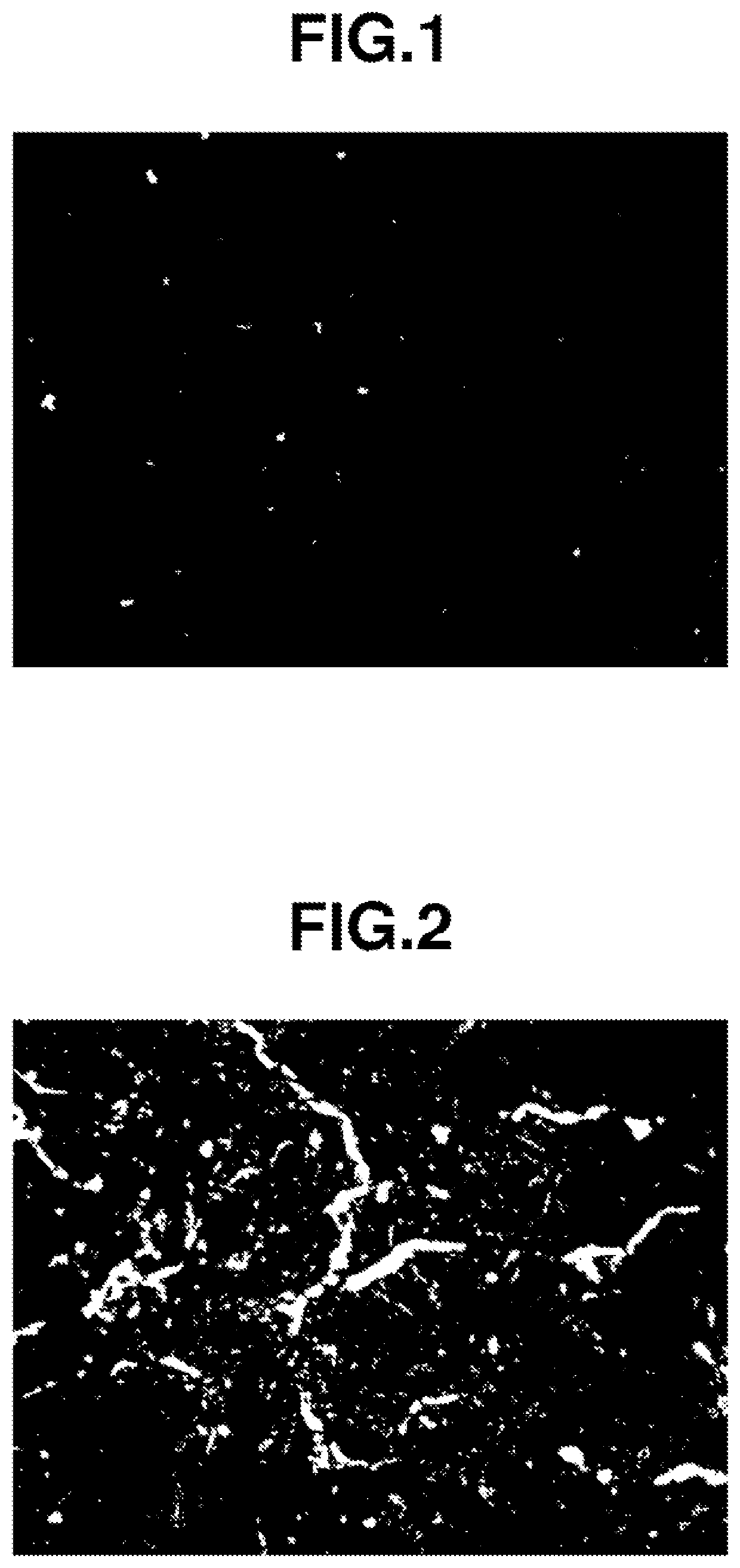
[0074]The resin films for impregnation were placed on the upper and lower faces of the porous sheet A, and the stack was allowed to stand at 185° C. for 5 minutes, to obtain fuel cell separator precursor A. A metallograph of the fuel cell separator precursor A is shown in FIG. 1. The fuel cell separator precursor A was confirmed to have the organic fiber not so much appeared on the surface thereof, and to have an electroconductive filler layer formed thereon.
[0075]The fuel cell separator precursor A was then subjected to compression molding with a molding pressure kept at 47 MPa, under natural cooling from a die temperature of 185° C. down to 100° C., to thereby obtain fuel cell separator A (0.17 mm thick).
PUM
| Property | Measurement | Unit |
|---|---|---|
| glass transition point | aaaaa | aaaaa |
| particle size | aaaaa | aaaaa |
| particle size | aaaaa | aaaaa |
Abstract
Description
Claims
Application Information