Cover glass and in-cell liquid-crystal display device

a liquid crystal display device and cover glass technology, applied in non-linear optics, instruments, coatings, etc., can solve the problems of liquid crystal display screen opacification when touched with a finger, in-cell liquid crystal display devices, and increased thickness and weight of types, so as to prevent opacification, prevent opacification, and high mobility

Pending Publication Date: 2020-11-26
ASAHI GLASS CO LTD
View PDF0 Cites 15 Cited by
  • Summary
  • Abstract
  • Description
  • Claims
  • Application Information

AI Technical Summary

Benefits of technology

[0163]The cover glass 1 is less apt to have surface defects attributable to P and is less apt to suffer local electrification due to surface defects, since the tensile stress layer 27 has a P2O5 content of 2 mol % or less (about 5 mass % or less). Because of this, the cover glass 1 is less apt to suffer frictional electrification even when fingers of the user, etc. come into contact with the surface. The cover glass 1, after having been incorporated into display devices, can prevent opacification due to electrostatic charges.
[0164]The tensile stress layer 27 of the cover glass 1 satisfies that A×B is 135 or larger when the total concentration of Li2O, Na2O, and K2O, among the oxide components constituting the tensile stress layer 27, is A mol % and the concentration of Al2O3 among these is B mol %, or that C×D is 240 or larger when the total concentration of Li2O, Na2O, and K2O, among the oxide components constituting the tensile stress layer, is C mass % and the concentration of Al2O3 among these is D mass %. Consequently, since the cover glass 1 contains at least a certain amount of Li2O, Na2O, and K2O, which do not contribute to the formation of glass network and which have high mobility and combine with electrostatic charges to perform charge neutralization, the cover glass 1 is less apt to suffer frictional electrification even when fingers of the user, etc. come into contact with the surface. Because of this, the cover glass 1 is less apt to suffer frictional electrification even when fingers of the user, etc. come into contact with the surface, and can prevent opacification due to electrostatic charges after having been incorporated into display devices.
[0165]Furthermore, the cover glass 1 contains at least a certain amount of Al2O3 which contributes to network formation and which is close to Li2O, Na2O, and K2O. Hence, Li2O, Na2O, and K2O come into the network to enlarge the distance. Because of this, the Li2O, Na2O, and K2O are more movable, and the cover glass 1 is less apt to suffer frictional electrification even when fingers of the user, etc. come into contact with the surface. Consequently, the cover glass 1 is less apt to suffer frictional electrification even when fingers of the user, etc. come into contact with the surface, and can prevent opacification due to electrostatic charges after having been incorporated into display devices.
[0166]The cover glass 1 is inhibited from being frictionally charged, by the properties of the chemically strengthened glass 2. There is hence no need of disposing an electroconductive layer for charge neutralization, and the cover glass 1 can prevent opacification without increasing the thickness of the display device or the number of steps for production.
[0167]The compressive stress layers 25 and 32 of the cover glass 1 each have a depth DOL of 20 μm or larger. Because of this, in the case where an external shock is given to the cover glass 1, a deformation due to the shock is less apt to be transmitted to the tensile stress layer, resulting in enhanced impact resistance.
[0168]In the case where the first main surface 21 of the cover glass 1 has an area of 18,000 mm2 or larger and when the surface of the anti-fingerprint treated layer has a frictional electrification amount of 0 kV or less and −1.5 kV or more, then the cover glass 1, in which the first main surface 21 and the second main surface 22 each have an area as large as 18,000 mm2 or above, is less apt to suffer frictional electrification even when fingers of the user, etc. come into contact with the surface. Because of this, the cover glass 1, after having been incorporated into display devices, can prevent opacification due to electrostatic charges. Such frictional electrification amounts are hence preferred.

Problems solved by technology

However, there is a problem in that this type has an increased thickness and an increased weight.
Meanwhile, in-cell liquid-crystal display devices (in particular, IPS liquid-crystal display devices) have a problem in that the liquid-crystal display screen partly opacifies when touched with a finger.

Method used


Image

  • Cover glass and in-cell liquid-crystal display device
  • Cover glass and in-cell liquid-crystal display device
  • Cover glass and in-cell liquid-crystal display device

Examples


modification examples

[0170]The present invention is not limited to the embodiments only, and various improvements, design changes, and the like are possible within the gist of the invention. The specific procedures, structures, etc. for carrying out the present invention may be other structures, etc. so long as the object of the present invention can be achieved.

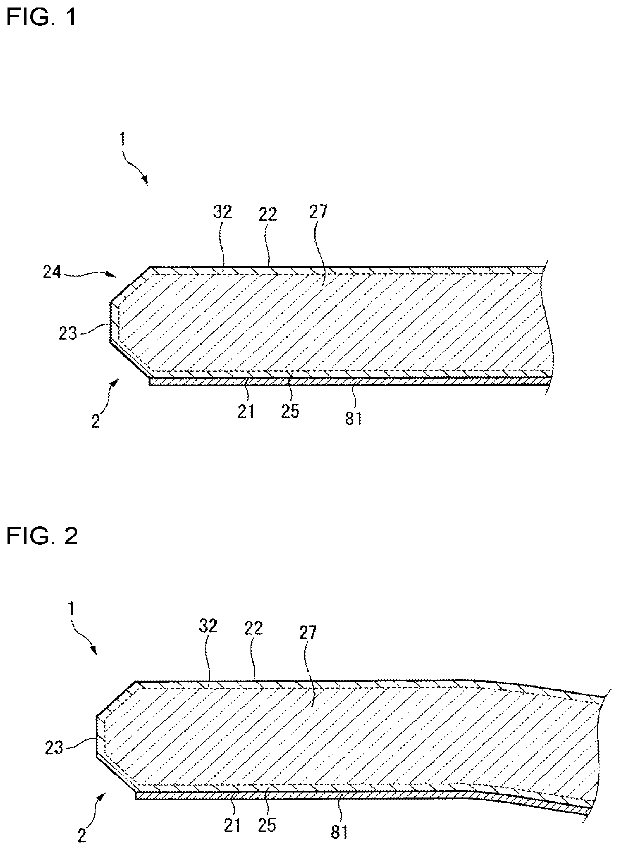
[0171]The shape of the chemically strengthened glass 2 is not limited to a sheet having flat surfaces only, and may be a sheet at least partly having a cured surface or a sheet having a recess. For example, the chemically strengthened glass 2 may be a bent glass such as that shown in FIG. 2. In the case where a bent glass is used, attachment of the cover glass 1 to a mating member does not result in a decrease in attachment accuracy even when the mating member has a bent shape.

[0172]The thickness of the chemically strengthened glass 2 is preferably 0.5 mm or larger. Use of the glass having a thickness of 0.5 mm or larger has an advantage in that...

example 1

[0223]First, a glass having the composition shown as Example 1 in Table 1 was produced by the float process to obtain a 0.7-mm glass sheet as a glass to be chemically strengthened. The glass obtained was cut into a size with a width of 100 mm and a length of 120 mm (area of the first main surface, 12,000 mm2), a size with a width of 100 mm and a length of 180 mm (area of the first main surface 21, 18,000 mm2), and a size with a width of 100 mm and a length of 260 mm (area of the first main surface 21, 26,000 mm2).

[0224]Next, these glasses were chemically strengthened. The chemical strengthening was conducted under the conditions of 8-hour immersion in 100 wt % molten potassium nitrate salt having a temperature of 420° C.

[0225]The strengthened glasses were cleaned. Thereafter, a liquid obtained by diluting A fluid S-550, manufactured by AGC Inc., with fluorochemical solvent ASAHIKLIN AC-6000, manufactured by AGC Inc., to 0.1 mass % was applied to one surface of each glass by spray co...

example 2

[0242]Raw materials were mixed so as to result in a glass having the composition shown as Example 2 in Table 1. The raw-material mixture was melted, poured so as to give a block about 300 mm square, and then gradually cooled to obtain a glass object as a glass to be chemically strengthened. Thereafter, the glass object was cut and machined to obtain plate-shaped glasses respectively having: a width of 100 mm, a length of 120 mm, and a thickness of 0.7 mm; a width of 100 mm, a length of 180 mm, and a thickness of 0.7 mm; and a width of 100 mm, a length of 260 mm, and a thickness of 0.7 mm.

[0243]Next, these glasses were chemically strengthened. The chemical strengthening was conducted under such conditions that the glasses were immersed for 3 hours in 100 wt % molten sodium nitrate salt having a temperature of 450° C. and then immersed for 3 hours in 100 wt % molten potassium nitrate salt having a temperature of 450° C.

[0244]Thereafter, the glasses were treated under the same conditio...


PUM

PropertyMeasurementUnit
areaaaaaaaaaaa
areaaaaaaaaaaa
areaaaaaaaaaaa

Abstract

A cover glass includes a chemically strengthened glass including a first main surface having an area of 12,000 mm2 or larger and a second main surface, and an anti-fingerprint treated layer provided on or above the first main surface. The chemically strengthened glass has a depth of compressive stress layer DOL of 20 μm or larger, has a tensile stress layer having a P2O5 content of 2 mol % or less, and has A×B of 135 or larger, provided that, among oxide components constituting the tensile stress layer, a total concentration of Li2, Na2O, and K2O is A mol % and a concentration of Al2O3 is B mol %. The anti-fingerprint treated layer includes a surface having a frictional electrification amount, as determined by Method D described in JIS L1094:2014, of 0 kV or less and −1.5 kV or more.

Description

TECHNICAL FIELD[0001]The present invention relates to a cover glass and an in-cell liquid-crystal display device.BACKGROUND ART[0002]Some electronic appliances having a liquid-crystal display device, such as automotive navigation systems for mounting on vehicles, are equipped with a touch function. The touch function herein is a function whereby information is inputted by an operator by bringing a finger into contact with or close to the surface (cover glass) of the display device.[0003]Among structures for rendering the touch function possible is an outside type (out-cell) which includes a liquid-crystal display device and a touch panel attached thereto.[0004]The outside type is excellent in terms of yield because even in the case where either the liquid-crystal display or the touch panel is a failure, the remainder is usable. However, there is a problem in that this type has an increased thickness and an increased weight.[0005]An on-cell liquid-crystal display device has come to b...

Claims


Application Information

Patent Timeline
Patent Type & Authority Applications(United States)
IPC IPC(8): C03C4/18C03C21/00C03C17/42C03C3/097C03C3/085C03C3/087C03C3/091
CPCC03C2217/734C03C2218/151C03C3/091C03C3/087C03C21/002C03C2204/00C03C3/097C03C17/42C03C2217/75C03C3/085C03C4/18C03C2218/112B32B7/025B32B17/06C03C17/34G02F1/1333C03C17/32C03C17/30C03C17/3668C03C17/3657C03C21/00C03C2217/73C03C2217/76
Inventor TAKEDA, YOSUKEKOIKE, AKIOIKEDA, TORUSAITO, YASUNARIFUKAWA, MAKOTOMURAKAMI, TAKAAKI
Owner ASAHI GLASS CO LTD
Why Eureka
Try Eureka