Supercharge Your Innovation With Domain-Expert AI Agents!

Brake caliper tool

Active Publication Date: 2020-12-17
A&E DESIGN
View PDF0 Cites 2 Cited by
  • Summary
  • Abstract
  • Description
  • Claims
  • Application Information

AI Technical Summary

Benefits of technology

The patent relates to a tool for servicing brakes on vehicles. It is designed to retract the piston in a disc brake caliper assembly that contains brake pads. The tool uses a threaded stud and a coupler to move a pressure plate that helps to release the brakes when they need to be. The tool is easy to use and helps to keep brakes safe and functional.

Problems solved by technology

However, with a continuous wearing to the linings of the brake pads, the piston gradually travels outwardly into the interior of the caliper housing to make the space of accommodating the brake pads progressively narrower.
A difficulty with these tools, however, is the manual effort often required to effect retraction of the one or more pistons associated with the caliper housing.

Method used


Image

  • Brake caliper tool
  • Brake caliper tool
  • Brake caliper tool

Examples


Embodiment Construction

[0012]Although the disclosure hereof is detailed and exact to enable those skilled in the art to practice the invention, the physical embodiments herein disclosed merely exemplify the invention which may be embodied in other specific structures. While the preferred embodiment has been described, the details may be changed without departing from the invention, which is disclosed in the application.

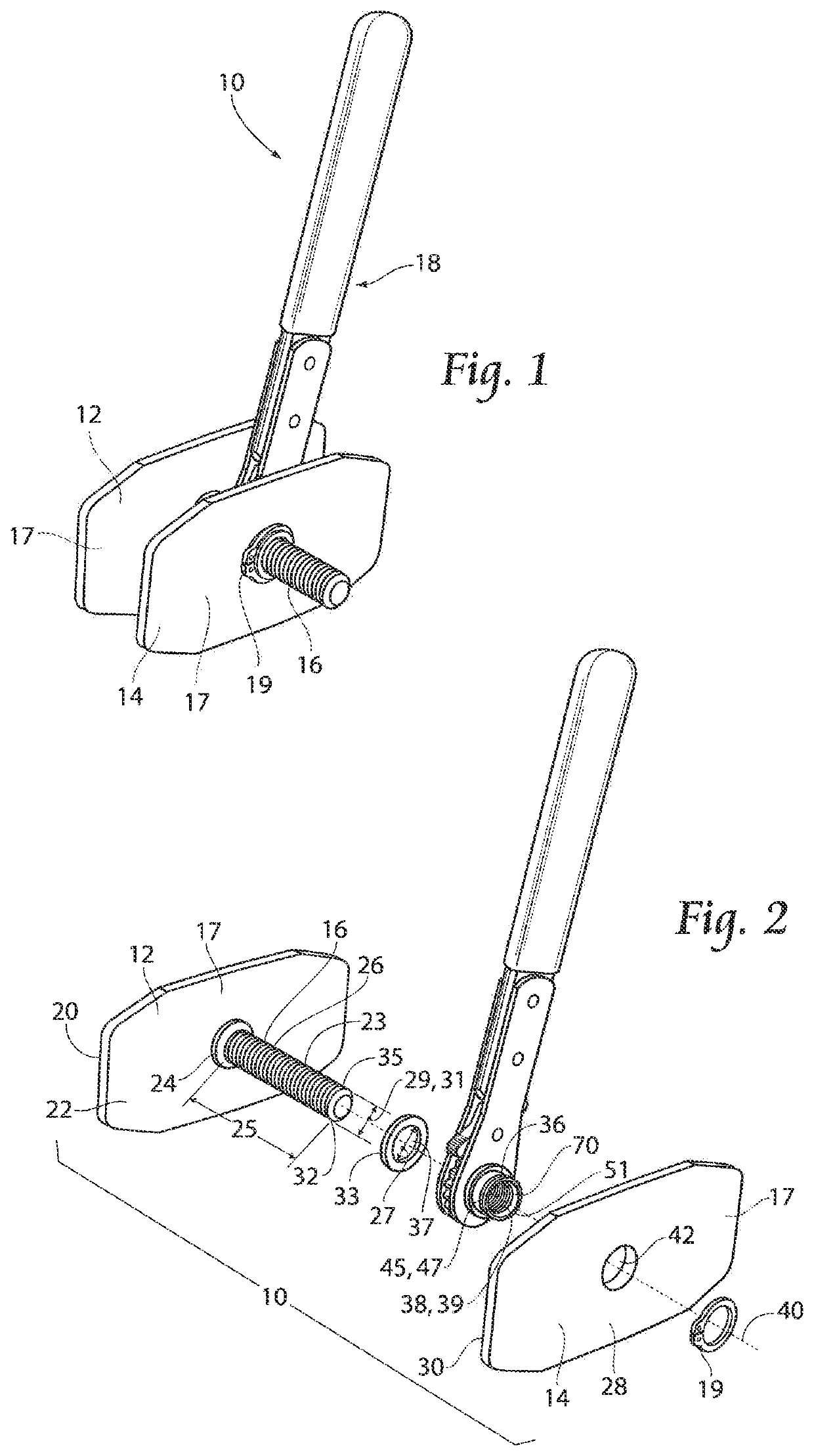
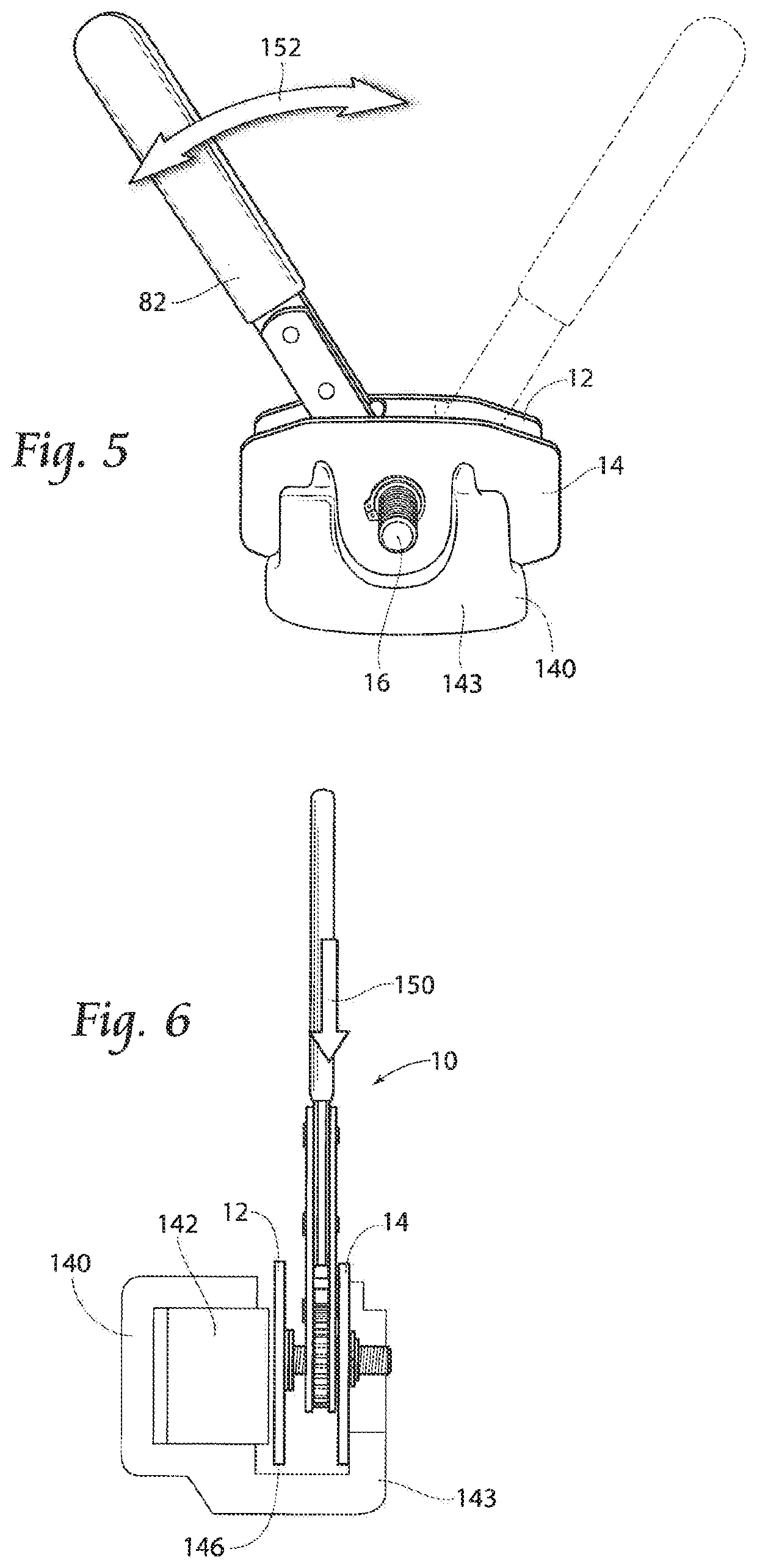
[0013]Referring now to the drawings, FIG. 1 illustrates a hand tool in the form of a disc brake piston retractor tool 10 used for compressing one or more pistons 142 (See FIGS. 6, 7) into a caliper housing 140 (See FIGS. 6, 7) when replacing a set of brake pads installed therein.

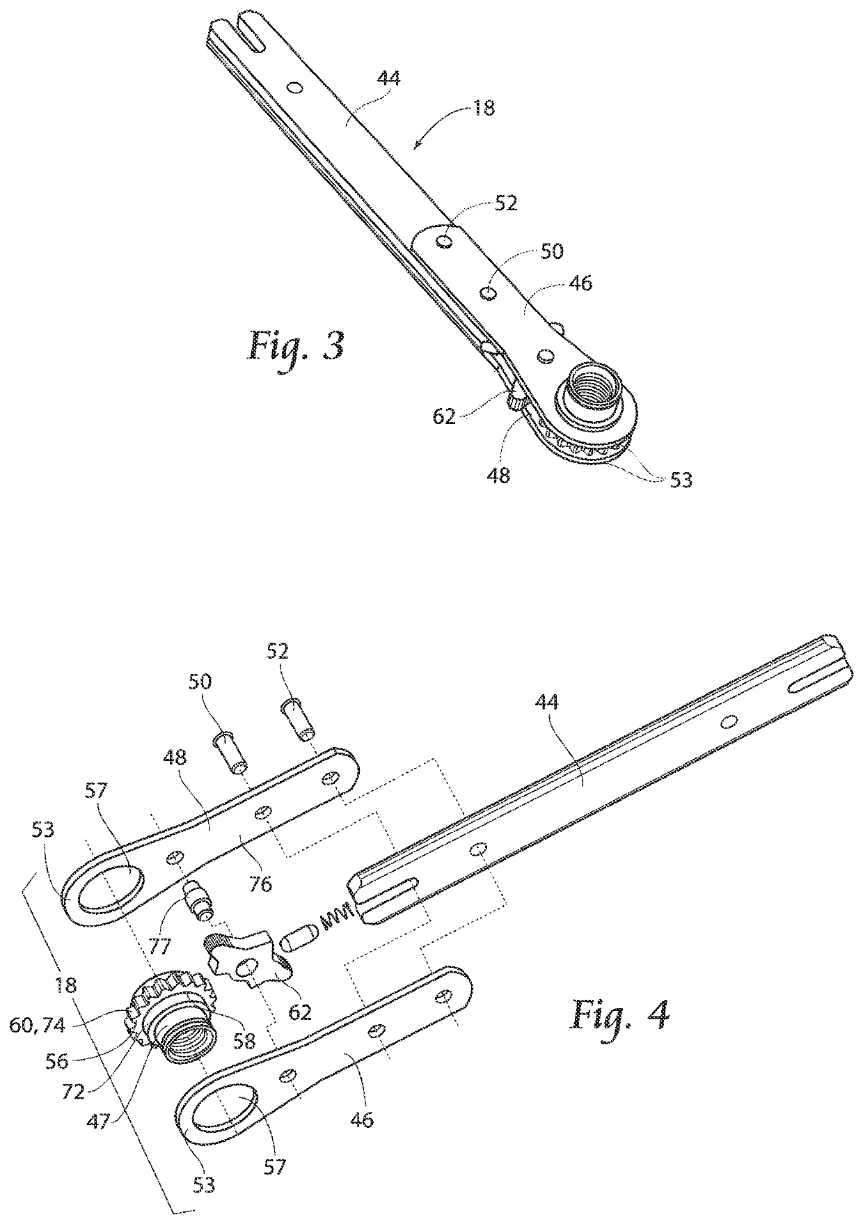
[0014]The disc brake piston retractor tool 10 is generally comprised of a first pressure plate 12, a second pressure plate 14, a coupler 36 (See FIG. 2) interconnecting the first and second pressure plates (12, 14), a reversible ratchet wrench assembly 18 connected to the coupler 36, and a snap ring 10 removably con...


PUM


Abstract

A tool for retracting pistons into cylinder bores is disclosed, with a narrow gap between facing pressure plates allowing use of the tool in tight places, and ratcheting spreading of the facing pressure plates causing outward moving of the pistons, enabling work to be performed, wherein movement of a threaded stud through a coupler moves a first pressure plate.

Description

BACKGROUND OF THE INVENTION[0001]In the repair of motorcycles and smaller automotive vehicles and, more particularly, with respect to the repair of vehicle braking systems, having disc brakes, various special tools are desirable. Disc brakes typically include a caliper housing which is positioned adjacent a vehicle wheel assembly having a rotor or brake disc rotatably mounted therewith. The caliper housing is associated with at least one piston which moves back and forth in a cylinder, and includes a pair of opposed brake pads for clamping the rotor in response to movement of the piston. When a vehicle operator activates a foot brake or a handle brake, brake fluid is forced from a master cylinder into the cylinder associated with the caliper housing to push the piston(s), and force engagement of the brake pads against the rotor to stop rotation of the wheel. When linings of the brake pads are worn too thin under a certain thickness after a period of use, the brake pads are required ...

Claims


Application Information

Patent Timeline
IPC IPC(8): F16D65/00B25B27/00B25B13/46
CPCB25B27/0035F16D65/0043B25B13/46B25B13/463B25B27/0021B25B27/023F16D65/0068
Inventor DAHL, VINCENTKUZMIC, JEFFREY J.ALHO, TIMOTHY J.
Owner A&E DESIGN
Features
  • R&D
  • Intellectual Property
  • Life Sciences
  • Materials
  • Tech Scout
  • Unparalleled Data Quality
  • Higher Quality Content
  • 60% Fewer Hallucinations
Learn More