Check patentability & draft patents in minutes with Patsnap Eureka AI!

Induction-type rotation detection device

a detection device and induction-type technology, applied in the direction of electric/magnetic position measurement, instruments, transportation and packaging, etc., can solve the problems of difficult to reduce the size of movable sections, etc., to promote the downsizing the construction of the rotation detection device can be simplified, and the effect of simple and compact construction

Active Publication Date: 2020-12-31
AMITEQ
View PDF0 Cites 0 Cited by
  • Summary
  • Abstract
  • Description
  • Claims
  • Application Information

AI Technical Summary

Benefits of technology

The present invention relates to a rotation detection device that has a simple and compact construction, making it suitable for downsizing. The device detects rotation of a rotation shaft using a magnetically responsive member that is formed in a line-shaped pattern varying cyclically in the rotational axis direction. The secondary coil in the stator is constructed to form a loop pattern of multiple cycles along the circumference of the rotating member, making it compactly along the member. This allows for a smaller and more compact stator to be provided. The rotation detection device is suitable for being integrated into a machine or apparatus that is the object of rotation detection. The stator only needs to include the secondary coil without the need for a dedicated primary coil. This simplifies the construction of the rotation detection device. The magnetically responsive member and the secondary coil are designed to be compact and efficient, eliminating the need for a transmission gear mechanism and improving control performance.

Problems solved by technology

However, the coil disposed on the flat substrate as disclosed in Patent Literatures 1 to 6 is not so suited for a rotational position detection device although it is suited for a linear position detection device.
Further, with the aforementioned construction where the area or volume of the magnetically responsive member varies in response to the position of the object of detection, it is difficult to reduce the size of, or downsize, a movable section.
Furthermore, with the combination of the torque sensor and the rotation detection device as disclosed in Patent Literatures 7 to 12, where the sensor and the rotation detection device are provided as separate independent components, simplifying the construction of the device is limited.
Furthermore, with the construction in which the transmission gear mechanism is provided between the rotation shaft and the rotation detection device, there is a possibility of control performance being deteriorated due to wobbling resulting from gear backlashes.
Furthermore, because no transmission gear mechanism has to be provided in the composite-type rotation detection device, there is no possibility of control performance being deteriorated due to wobbling resulting from gear backlashes.

Method used


Image

  • Induction-type rotation detection device
  • Induction-type rotation detection device
  • Induction-type rotation detection device

Examples


Embodiment Construction

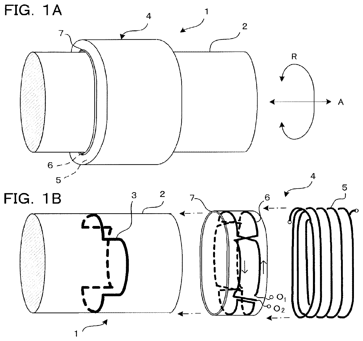
[0032]FIG. 1A is a schematic perspective view illustrating an outer appearance of a rotation detection device 1 according to an embodiment of the present invention, and FIG. 1B is a schematic exploded perspective view illustrating, in an unfolded or developed manner, principal sections of the rotation detection device 1. The rotation detection device 1, which is constructed to detect a rotational position of a rotating member 2, includes a magnetically responsive member 3 disposed on the rotating member 2 along the circumference of the rotating member 2 in such a manner that the magnetically responsive member 3 rotates together with the rotating member 2, and a stator 4 provided along the circumference of the rotating member 2 in a contactless manner. In FIG. 1A, arrow R denotes a rotational direction of the rotating member 2, and arrow A denotes a rotational axis direction of the rotating member 2. The magnetically responsive member 3 is formed in a line-shaped pattern varying cycl...


PUM

PropertyMeasurementUnit
circumferenceaaaaaaaaaa
AC magnetic fieldaaaaaaaaaa
rotationaaaaaaaaaa

Abstract

A magnetically responsive member is disposed on a rotating member along the circumference of the rotating member in such a manner that the magnetically responsive member rotates together with the rotating member, and the magnetically responsive member is formed in a line-shaped pattern varying cyclically in a rotational axis direction. A stator is disposed around the rotating member in a contactless manner, and the stator includes a primary coil wound around the rotating member, and a secondary coil forming a loop pattern of a plurality of cycles along the circumference of the rotating member. As the primary coil is AC-energized, an induced AC output signal corresponding to relative positions between the line-shaped pattern of the rotating member and the loop pattern of the secondary coil, which depend on a rotational position of the rotating member, is output from the secondary coil.

Description

TECHNICAL FIELD[0001]The present invention relates to an induction-type rotation detection device and to a composite-type detection device that detects rotation of a rotation shaft through combination between the induction-type rotation detection device and a torque sensor for detecting torque of the rotation shaft and that is applicable to detection of rotation of a pedal crankshaft of an electric power-assisted bicycle, rotation of a steering shaft of an automotive vehicle, and the like.BACKGROUND[0002]There have heretofore been known various types of position detection devices that use a coil (inductance element) as a position detecting element. It has also been known to use a flat coil rather than an ordinary cylindrical coil, with a view to reducing the size of, or downsizing, a device construction. As an example, the detection device disclosed in Patent Literature 1 identified below uses, as a detecting element, a small flat coil disposed in a spiral shape on a printed circuit...

Claims


Application Information

Patent Timeline
Patent Type & Authority Applications(United States)
IPC IPC(8): G01B7/30G01L3/10G01B7/00B62M6/50B62M6/55G01D5/20
CPCB62M6/50G01D5/204B62M6/55G01B7/30G01L3/105G01B7/003G01D5/2006G01P3/488
Inventor GOTO, DAISUKESAKAMOTO, KAZUYA
Owner AMITEQ
Features
  • R&D
  • Intellectual Property
  • Life Sciences
  • Materials
  • Tech Scout
  • Unparalleled Data Quality
  • Higher Quality Content
  • 60% Fewer Hallucinations
Learn More