Winged hammer tip

US20210001346A1Active Publication Date: 2021-01-07BELLOTA AGRISOLUTIONS & TOOLS USA LLC

Image

  • Winged hammer tip
  • Winged hammer tip
  • Winged hammer tip

Examples


Embodiment Construction

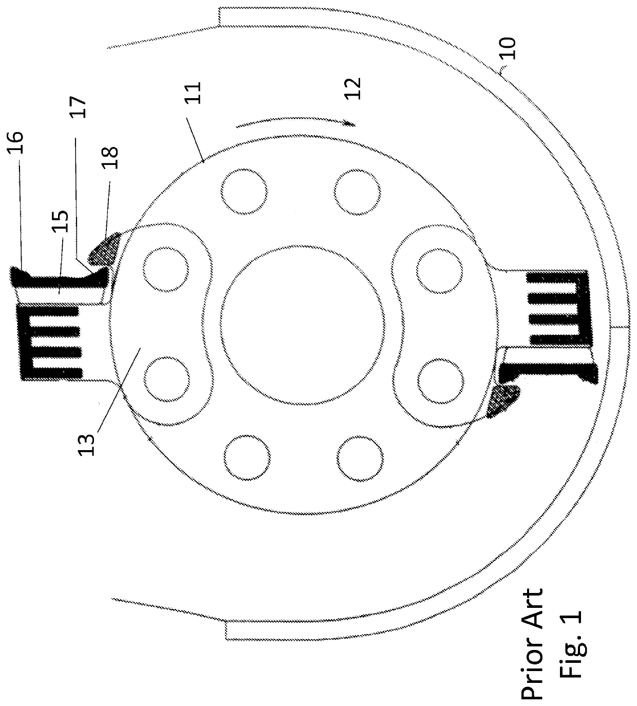
[0070]FIG. 1 is a prior art side view of a grinding machine assembly. The grinder housing 10 is stationary. The drum 11 is powered and has rotation direction 12. The hammer 13 is affixed to the drum 11.

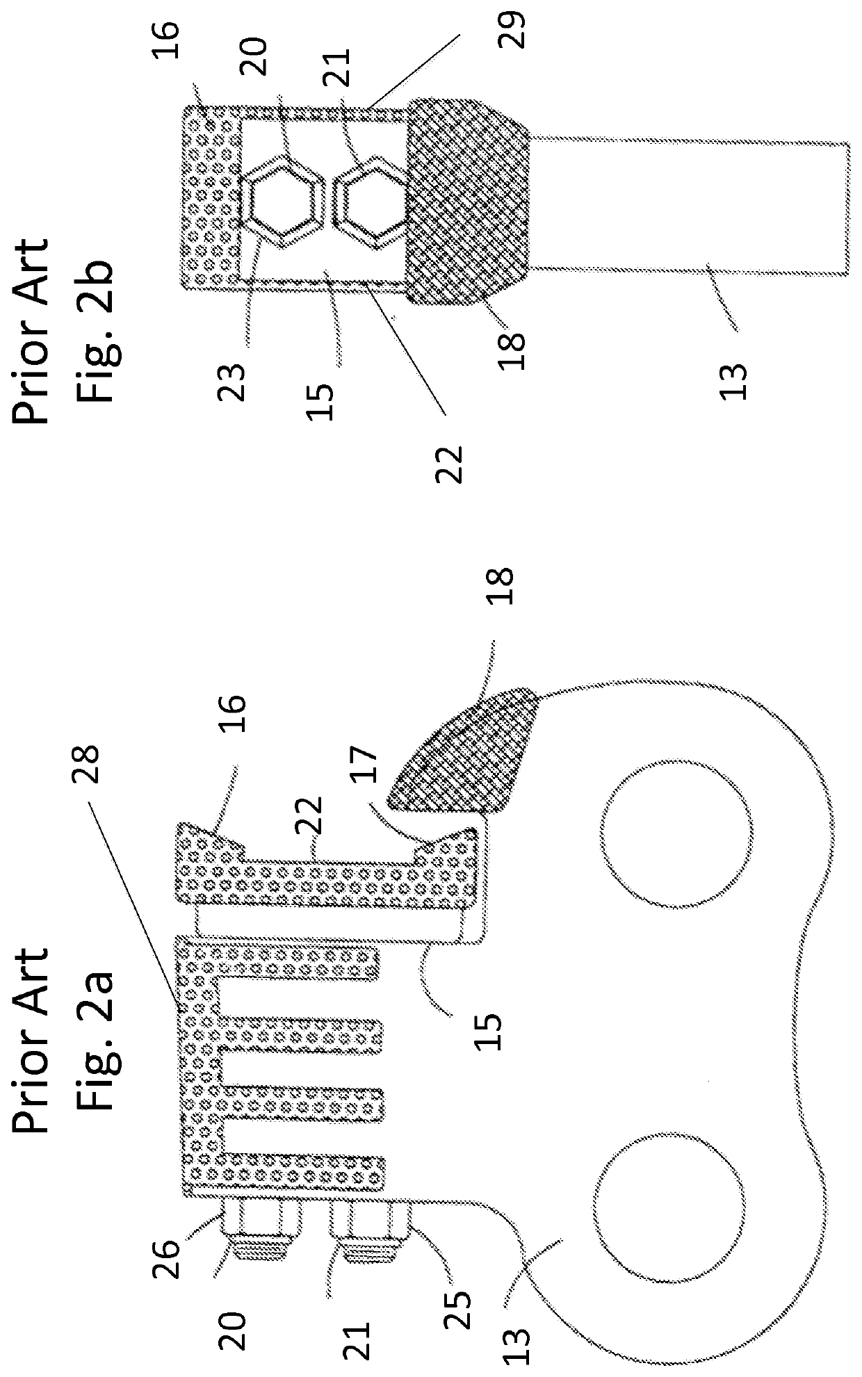
[0071]FIG. 2a is a prior art side view of a hammer assembly. The hammer tip 15 is affixed to the hammer 13 with bolt 21, bolt 20, nut 25 and nut 26. A bolt pocket 23 is incorporated into the hammer tip 15. The hammer tip 15 includes distal working edge 16, distal working edge 17, proximal working edge 22 and proximal working edge 29.

[0072]The nose 18 incorporated into the hammer 13 is intended to protect the distal working edge 17 from wear while in this position. After several hours of grinder operation, the distal working edge 16 would experience wear to the point that the grinder throughput is decreased. Then bolt 20 and bolt 21 would be removed, the hammer tip 15 would be inverted and the bolts replaced.

[0073]A wear resistant surface 28 such as Caden Edge is shown on the nose 18, ...


PUM


Abstract

A hammer tip for releasable integration with a hammer, used in a size reducing machine. The hammer tip is separated into a production block with a top working edge and a spacer block. The production block and spacer block utilize a saddle back attachment to the hammer. The production block is further supported with a lock ledge integration to the spacer block. The spacer block further includes a pair of wings extending outwardly from the left and right sides, and forwardly from the front side, of the spacer block to form additional cutting edges. The wings provide for additional sizing of the material being ground and help move (or push or carry) more material through the grates of the size reducing machine in the same amount of time as compared to spacer blocks without wings. This increased throughput improves efficiency of the size reducing machine.

Description

CROSS-REFERENCE TO RELATED APPLICATIONS[0001]This application is a continuation-in-part of U.S. patent application Ser. No. 14 / 708,945, filed May 11, 2015, titled “Production Plus Hammer Tip,” which claims the benefit of and priority to U.S. Provisional Patent Application No. 61 / 993,335, filed May 15, 2014, titled “Production Plus Hammer Tip,” the contents of which are incorporated herein by reference.FIELD OF INVENTION[0002]The present invention relates to a hammer tip for releasable integration with a hammer, used in a size reducing machine.BACKGROUND[0003]Size reducing machines include rotary hammer mills, tub grinders, vertical and horizontal feed machines and the like. These machines include a plurality of hammers with replaceable hammer tips. Common design practice is for the hammer tips to be symmetrical with two top working edges. It is also common for the hammer tip to be attached to the hammer with two bolts and two nuts. U.S. Pat. No. 6,419,173 granted to Balvanz shows th...

Claims


Application Information

Patent Timeline
07 Jan 2021
Publication
US20210001346A1
IPC
B02C13/28
CPC
B02C13/2804; B02C2210/02
Inventors
BALVANZ, LORAN R.