Supercharge Your Innovation With Domain-Expert AI Agents!

Drive train for a motor vehicle having a directly cooled electric machine and a transmission, and a motor vehicle

a technology for driving trains and motor vehicles, which is applied in the direction of electric devices, vehicle sub-unit features, battery/fuel cell control arrangements, etc., can solve the problems of high friction loss in electric machines, limited continuous power of drive trains with electric machines, and unnecessary weight, so as to prevent coolant and reduce the effect of friction loss, good geometric adaptation, and reliable sealing of air gaps

Active Publication Date: 2021-01-07
DR ING H C F PORSCHE AG
View PDF15 Cites 3 Cited by
  • Summary
  • Abstract
  • Description
  • Claims
  • Application Information

AI Technical Summary

Benefits of technology

The invention allows for efficient cooling and lubrication of the electric machine and transmission without the need for a separate lubricant. The number of fluids in the vehicle is reduced, saving money and minimizing faults. The electric machine cools effectively without the need for a separate heating system, improving efficiency at start-up. The cooling circuit can cool the rotor independently, allowing for more cost-effective cooling.

Problems solved by technology

The continuously available power of drive trains with electric machines usually is limited by the thermal limits of the electric machines.
However, high friction losses occur in the electric machine if the coolant enters the air gap between the stator and the rotor.
Using a coolant and an additional lubricant for the operation of the drive train is uneconomic and gives rise to unnecessary weight and requires a large amount of installation space.

Method used


Image

  • Drive train for a motor vehicle having a directly cooled electric machine and a transmission, and a motor vehicle
  • Drive train for a motor vehicle having a directly cooled electric machine and a transmission, and a motor vehicle
  • Drive train for a motor vehicle having a directly cooled electric machine and a transmission, and a motor vehicle

Examples


second embodiment

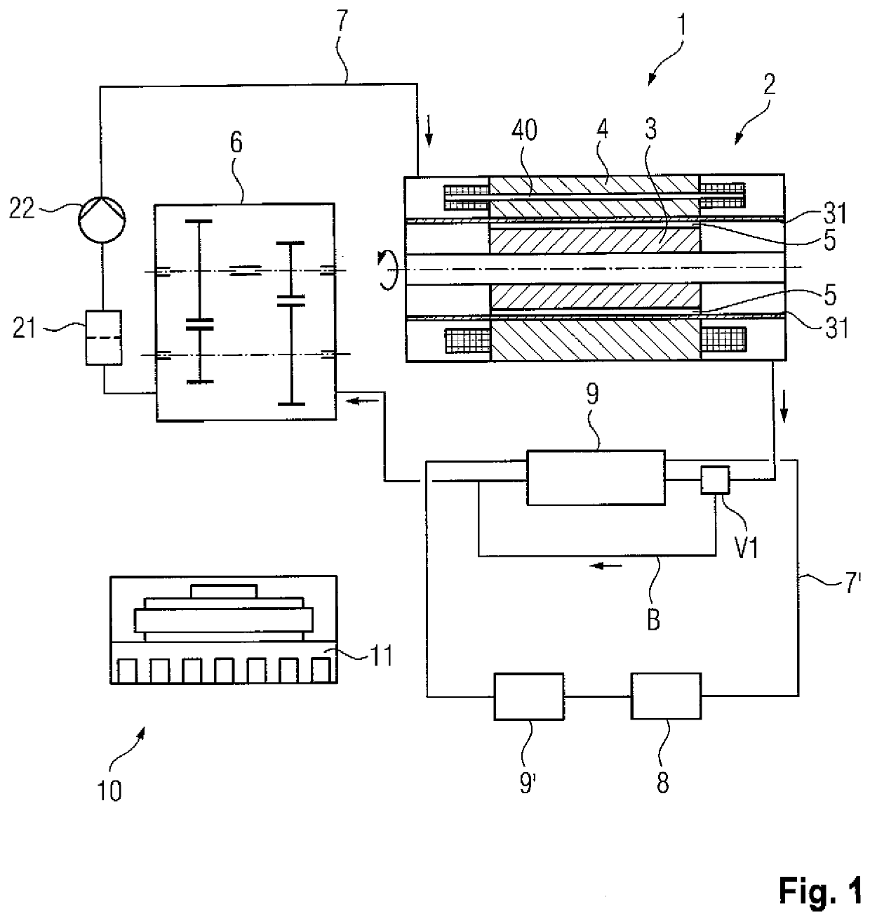
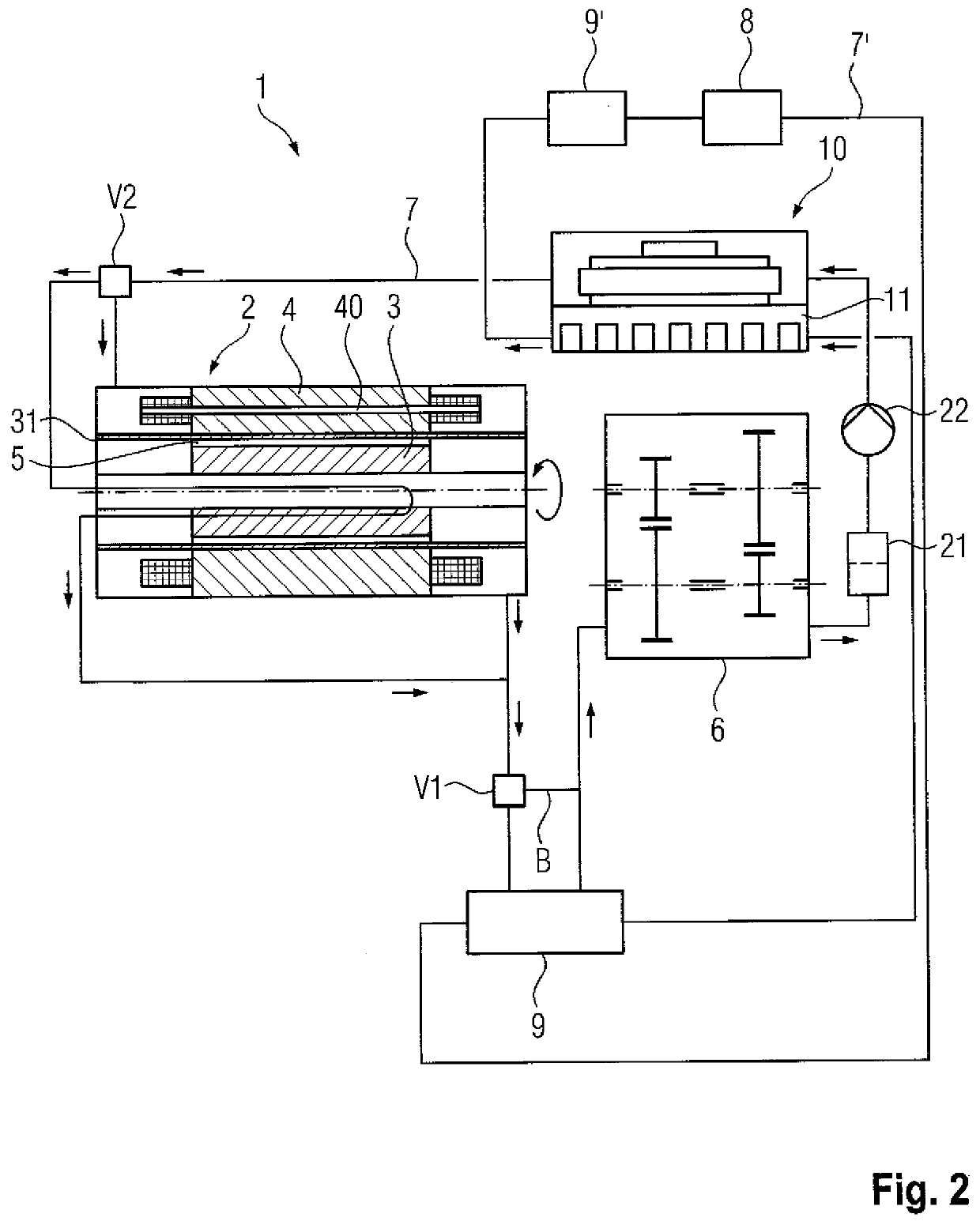
[0032]FIG. 2 is a schematic illustration of a drive train 1 according to the invention. The drive train 1 shown in FIG. 2 differs from the drive train 1 shown in FIG. 1 in that the coolant also flows through and cools the rotor 3. Also, the power electronics 10 are cooled both by the cooling circuit 7 and the further cooling circuit 7′.

[0033]The stator 4 and the rotor 3 are arranged in the cooling circuit 7 in such a way that coolant flows through them in parallel with one another. The further valve V2 can be adjusted in a gradual fashion to regulate the ratio of the throughflow of coolant through the stator 4 and the throughflow of coolant through the rotor 3 in such a way that the ratio is to the ratio of the quantity of heat to be dissipated. The quantity of heat of the stator 4 that is to be dissipated during operation of the drive train 1 is usually significantly larger than the quantity of heat of the rotor 3 that is to be dissipated. Thus, the throughflow of coolant through t...

third embodiment

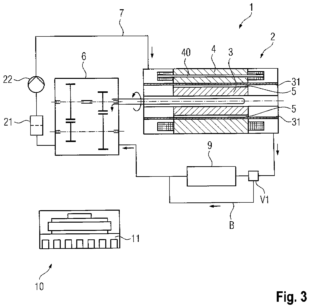
[0035]FIG. 3 is a schematic illustration of a drive train 1 according to the invention. The drive train 1 of FIG. 3 differs from the drive train 1 of FIG. 1 in that the coolant also flows through and cools the rotor 3. In this context, the coolant flows directly from the transmission 6 into the rotor 3. The transmission 6 forms a coolant reservoir, as it does also in the embodiments illustrated in FIGS. 1 and 2.

[0036]FIG. 4 is a schematic illustration of a motor vehicle 100 according to an embodiment of the invention with a drive train 1 according to an embodiment of the invention.


PUM


Abstract

A drive train (1) for a motor vehicle (100) has an electric machine (2) with a rotor (3), a stator (4) and an air gap (5) between the rotor (3) and the stator (4). The drive train (1) also has a transmission (6) and a cooling circuit (7) for conducting a coolant through the electric machine (2) and the transmission (6). The coolant is provided for lubricating and cooling the transmission (6) and for directly cooling electrical conductors of the stator (4). The cooling circuit (7) is provided in such a way that the coolant does not enter the air gap (5).

Description

CROSS REFERENCE TO RELATED APPLICATION[0001]This application claims priority under 35 USC 119 to German Patent Appl. No. 10 2019 117 893.2 filed on Jul. 3, 2019, the entire disclosure of which is incorporated herein by reference.BACKGROUNDField of the Invention[0002]The invention relates to a drive train for a motor vehicle having a directly cooled electric machine and a transmission, as well as a motor vehicle.Related Art[0003]The continuously available power of drive trains with electric machines usually is limited by the thermal limits of the electric machines. In addition to the heat resistance of the installed components, the cooling of the electric machine plays a decisive role. The dissipation of heat by fluid cooling is known from the prior art. For this purpose, a housing of the electric machine contains a cooling geometry through which a fluid coolant flows. The heat generated in the machine is dissipated into the coolant by means of heat conduction and convection.[0004]Th...

Claims


Application Information

Patent Timeline
Patent Type & Authority Applications(United States)
IPC IPC(8): B60K11/02B60L58/26H02K11/33H02K9/197H05K7/20
CPCB60K11/02B60L58/26H05K7/20927H02K9/197H02K11/33H02K5/128H02K7/10H02K7/006B60K1/00B60K2001/006B60Y2306/03B60K2001/005B60K2001/003B60Y2400/61Y02T10/70B60L3/003B60L2240/485B60L2240/425Y02T10/64
Inventor OECHSLEN, STEFAN
Owner DR ING H C F PORSCHE AG
Features
  • R&D
  • Intellectual Property
  • Life Sciences
  • Materials
  • Tech Scout
  • Unparalleled Data Quality
  • Higher Quality Content
  • 60% Fewer Hallucinations
Learn More