Operation processing apparatus and operation processing method

a processing apparatus and operation processing technology, applied in the direction of biological neural network models, instruments, processor architectures/configurations, etc., can solve the problems of high cost and high requirement of cnn processing hardware to execute processing at high speed, and achieve the effect of speeding up processing and reducing cos

Active Publication Date: 2021-01-07
CANON KK
View PDF4 Cites 2 Cited by
  • Summary
  • Abstract
  • Description
  • Claims
  • Application Information

AI Technical Summary

Benefits of technology

[0018]The present invention provides a technique in which when inputting input data to a hierarchical neural network to perform operation processing in each layer of the hierarchical neural network, it is possible to reduce the cost while speeding up the processing without degrading the processing performance.

Problems solved by technology

In the processing by the CNN, a number of convolution operations are repeated, and it is thus necessary to perform the product-sum operation an enormous number of times. As a result, the CNN processing hardware is required to execute the processing at high speed.
In addition, the memory of the CNN processing hardware and the shared memory are separately required, thereby increasing the cost.

Method used


Image

  • Operation processing apparatus and operation processing method
  • Operation processing apparatus and operation processing method
  • Operation processing apparatus and operation processing method

Examples


first embodiment

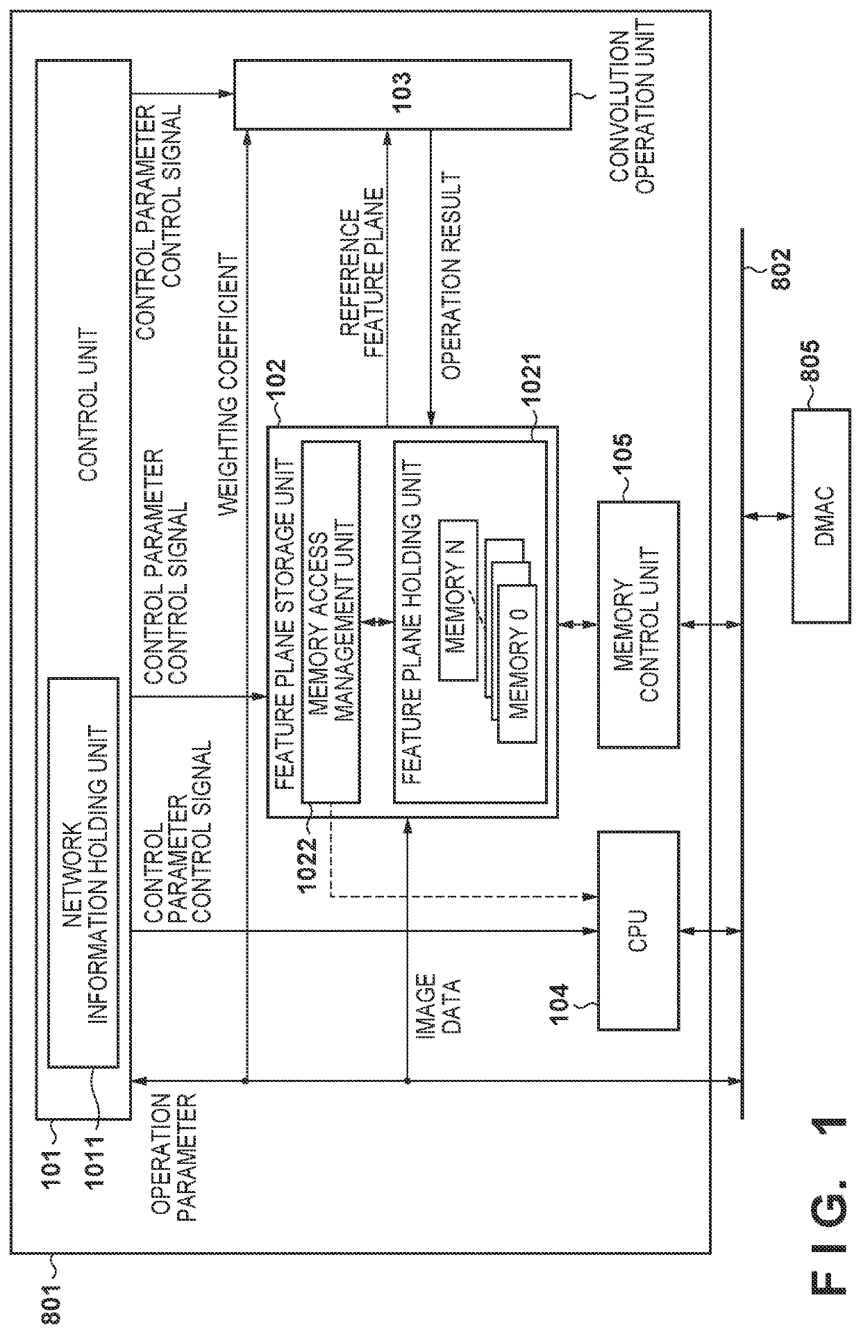
[0035]An example of the hardware arrangement of an image processing system using a recognition processing apparatus as an operation processing apparatus according to this embodiment will be described with reference to a block diagram shown in FIG. 8. The image processing system according to this embodiment has a function of detecting a region of a specific object from input image data.

[0036]An image input unit 800 acquires image data as input data by performing image capturing. The image data may be data of an image of each frame in a moving image or data of a still image. The image input unit 800 is formed by a driver circuit for controlling an optical system, a photoelectric conversion device such as a CCD (Charge-Coupled Devices) or CMOS (Complementary Metal Oxide Semiconductor) sensor, and a sensor, an AD converter, a signal processing circuit for controlling various kinds of image correction, a frame buffer, and the like.

[0037]A recognition processing unit 801 includes the reco...

second embodiment

[0101]The difference from the first embodiment will be described below, and the rest is assumed to be the same as in the first embodiment unless it is specifically stated otherwise. An example of the arrangement of a recognition processing unit 801 according to this embodiment will be described with reference to a block diagram shown in FIG. 11.

[0102]This embodiment assumes that feature planes in a processing target layer are successively stored in the raster order from a start address 0 in a continuous 48-KB region on a memory map. That is, in accordance with a horizontal size w and a vertical size h of each feature plane, an address A2 on the memory map of data of a feature plane with a feature plane number n at coordinates (x, y) is decided by:

A2=w×h×n(feature plane offset)×y×w(line offset)+x

[0103]A memory control unit 1051 uses an access request address as an address signal of an SRAM in an arrangement including one SRAM interface (one chip select). The SRAM interface is connec...


PUM


Abstract

An apparatus for, by inputting data to a hierarchical neural network and performing operation processing in each layer of the network, calculating a feature plane in the layer, comprises an operation unit, a feature plane holding unit including at least one memory that holds a feature plane to be processed, a unit configured to control to arrange the feature plane in the memory based on network information as information about each layer undergoing the operation processing and to manage reading / writing from / in the memory, and a processor configured to access, via a bus, the feature plane holding unit which is address-mapped in a memory space. The processor calculates, based on the network information, an address address-mapped in the memory space, reads out the feature plane, and processes the feature plane.

Description

BACKGROUND OF THE INVENTIONField of the Invention[0001]The present invention relates to a technique of calculating a feature plane in each layer of a hierarchical neural network by inputting input data to the hierarchical neural network to perform operation processing in the layer.Description of the Related Art[0002]A hierarchical operation method called a convolutional neural network (to be referred to as a CNN hereinafter) is receiving attention as a method of allowing pattern recognition robust to a variation of a recognition target. For example, various application examples and implementation examples are disclosed in Yann LeCun, Koray Kavukvuoglu and Clement Farabet: Convolutional Networks and Applications in Vision, Proc. International Symposium on Circuits and Systems (ISCAS′10), IEEE, 2010.[0003]FIG. 9 is a view showing an example of the network configuration of a simple CNN. Reference numeral 901 denotes an input layer which corresponds to image data of a predetermined size...

Claims


Application Information

Patent Timeline
Patent Type & Authority Applications(United States)
IPC IPC(8): G06N3/063G06N3/04
CPCG06N3/063G06N3/0454G06N3/045G06T1/20G06T1/60
Inventor WAKINO, SHIORI
Owner CANON KK
Why Eureka
Try Eureka