Flexible coal-fired power generation system and operation method thereof

a flexible coal-fired power generation and operation method technology, which is applied in the direction of preheating, machines/engines, light and heating apparatus, etc., can solve the problems of limited boiler minimum load, limited minimum output of coal-fired power generating units, and no reasonable solution for coal-fired power generating units, etc., to improve the low-load operating capacity of coal-fired power generation systems, improve energy efficiency, and improve the effect of operation flexibility

Active Publication Date: 2021-02-04
XI AN JIAOTONG UNIV
View PDF0 Cites 16 Cited by
  • Summary
  • Abstract
  • Description
  • Claims
  • Application Information

AI Technical Summary

Benefits of technology

[0017](1) The present invention realizes the decoupling of the steam turbine and the boiler by increasing the heat storage outside the coal-fired power generating unit, and greatly improves the operation flexibility of the coal-fired power generation system.
[0018](2) The present invention is able to adjust the flow of heat storage medium that flows into the heat storage medium heater. When the steam turbine requires to be operated at low load, the boiler combustion is able to be as unchanged as possible, and the heat storage medium is used to store the remaining high-grade energy outside the coal-fired power generating unit after meeting the load of the steam turbine, so as to improve the low-load operating capacity of the coal-fired power gene

Problems solved by technology

The strong coupling between the boiler and the steam turbine of the existing thermal system limits the minimum output of the coal-fired power generating unit.
At present, there is no reasonable solution for the coal-fired power generating unit to meet the requirements of the power grid for load cycling and low load operation performance.
(1) When wide-load operation is required, the steam turbine has good load regulating ability, but the minimum load

Method used


Image

  • Flexible coal-fired power generation system and operation method thereof

Examples


Embodiment Construction

[0021]The present invention is further explained with accompanying embodiments and drawings in detail as follows.

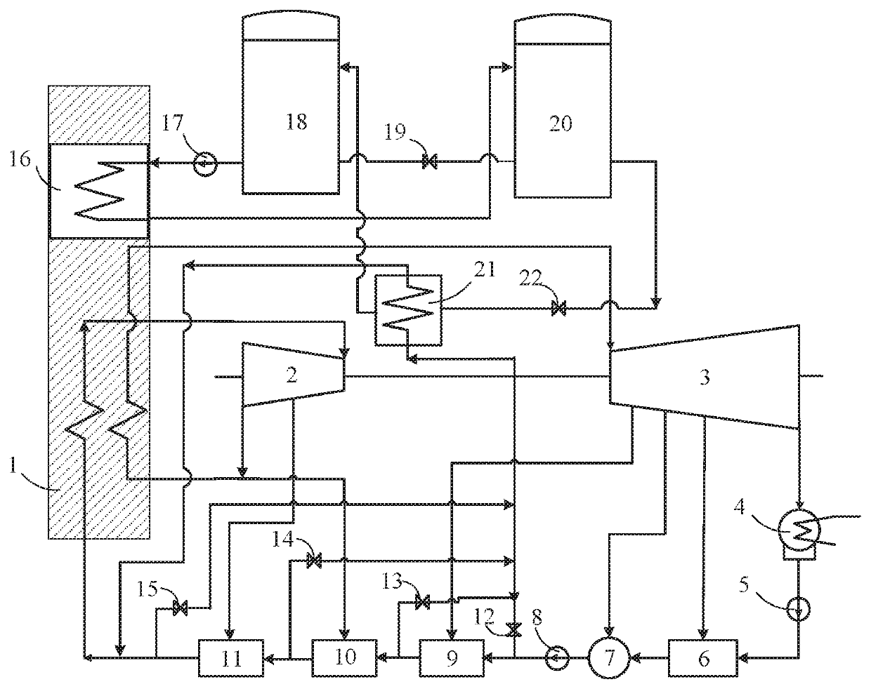
[0022]As shown in the drawing, a flexible coal-fired power generation system according to a preferred embodiment of the present invention is illustrated, which comprises a thermal system for coal-fired power generating unit and a high-temperature heat storage system, wherein:

[0023]the thermal system for coal-fired power generating unit comprises a boiler 1, a steam turbine high pressure cylinder 2, a steam turbine medium and low pressure cylinder 3, a condenser 4, a condensate pump 5, a low pressure heater 6, a deaerator 7, a feedwater pump 8, a first-stage high pressure heater 9, a second-stage high pressure heater 10, a third-stage high pressure heater 11, an inlet regulating valve 12 for the first-stage high pressure heater, an inlet regulating valve 13 for the second-stage high pressure heater, an inlet regulating valve 14 for the third-stage high pressure heater and ...


PUM


Abstract

A flexible coal-fired power generation system includes a thermal system for coal-fired power generating unit and a high-temperature heat storage system connected in parallel, wherein: the heat storage system includes a heat storage medium pump (17), a cold heat storage medium tank (18), a hot heat storage medium tank (20), multiple valves, and a heat storage medium and feedwater heat exchanger (21). A heat storage medium heater (16) locates in the boiler (1) and is connected with both the cold heat storage medium tank (18) and the hot heat storage medium tank (20). Through the heat storage medium pump (17), the flow of heat storage medium that enters the heat storage medium heater (16) is adjusted to reduce the output of the steam turbine when the boiler (1) is stably burning.

Description

CROSS REFERENCE OF RELATED APPLICATION[0001]This is a U.S. National Stage under 35 U.S.C 371 of the International Application PCT / CN2019 / 092427, filed Jun. 22, 2019, which claims priority under 35 U.S.C. 119(a-d) to CN 201910181229.2, filed Mar. 11, 2019.BACKGROUND OF THE PRESENT INVENTIONField of Invention[0002]The present invention relates to the field of coal-fired power generation technology, and more particularly to a flexible coal-fired power generation system and an operation method thereof.Description of Related Arts[0003]In power system of China, the installed capacity of the coal-fired power generating unit accounts for a large proportion, and the flexible peak-shaving power supply thereof accounts for a small proportion. Therefore, the increased peak shaving task after the merging of large-scale wind power, solar power and other new energy is mainly undertaken by the coal-fired power generating unit, which puts forward a new requirement for the flexibility of the coal-fir...

Claims


Application Information

Patent Timeline
IPC IPC(8): F01K11/02F01K13/02F01D15/10F01K17/02
CPCF01K11/02F01K17/02F01D15/10F01K13/02F01K3/205F01K7/38F01K7/40F05D2220/31F05D2220/64F22D1/325F22D1/34F01K7/22F01K7/36
Inventor YAN, HUILIU, MINGCHONG, DAOTONGWANG, JINSHICHEN, WEIXIONGYAN, JUNJIE
Owner XI AN JIAOTONG UNIV
Why Eureka
Try Eureka