Cooling tool for an extruder

a technology of extruder and cooling tool, which is applied in the direction of feeding-stuff, lighting and heating apparatus, applications, etc., can solve the problems of affecting the design of the cooling die, the inability to achieve a fibrous structure, and the inability to achieve a dense, compact, fibrous product structure, etc., and achieves excellent cooling characteristics and simple structure. , the effect of improving the cooling

Active Publication Date: 2021-02-18
BUEHLER AG
View PDF0 Cites 1 Cited by
  • Summary
  • Abstract
  • Description
  • Claims
  • Application Information

AI Technical Summary

Benefits of technology

[0008]It is therefore an object of the invention to overcome the abovementioned disadvantages, and in particular to provide a cooling tool which can reliably provide excellent cooling characteristics, while also having a simple structure and being easy to clean.

Problems solved by technology

A fibrous structure is not always easy to achieve, because an extrudate typically expands at the outlet of the extruder, and this is detrimental to a dense, compact, fibrous product structure.
However the design of these cooling dies still requires considerable improvement: by way of example, cooling is frequently insufficient and nonuniform, structure is excessively complex, and cleanability is unsatisfactory.
In these configurations there are problems with securing of the internal jacket.
This is achieved by way of example via bars, which however disrupt product flow.
Even when the bars are arranged before the end of the ingoing region of the cooling tool, for example in the distributor, homogeneous reconnection of strands, in particular of protein-containing extrudate, does not occur once they have been separated, and this adversely affects appearance and texture.
Bars in the end region of the cooling tool are also disadvantageous, because for reasons relating to strength they must be designed to have large volume, but they therefore cause substantial narrowing of the cross section of the product channel and likewise adversely affect the appearance and texture of the product.
This has a disadvantageous effect on homogeneity of flow velocity in the cooling tool, and this in turn has an adverse effect on the appearance and texture of the product.
These cooling tools moreover require disadvantageous design, because the force resulting from the pressure of the product imposes a bending moment on the smooth wall; the structure of the wall must therefore be more robust.
Designs of this type are structurally very complex, and the cooling of a plurality of discrete extrudate flow channels is also complicated and susceptible to defects arising from maintenance and from operation.

Method used


Image

  • Cooling tool for an extruder
  • Cooling tool for an extruder
  • Cooling tool for an extruder

Examples


Embodiment Construction

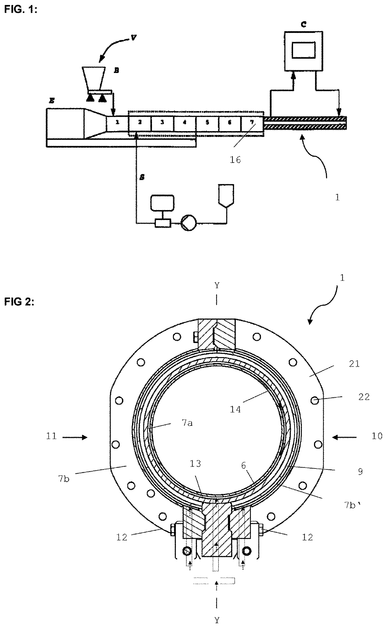
[0056]FIG. 1 shows schematically an extruder E composed of segments (1-7). A raw material V is introduced via the gravimetric metering system B. Water or steam is introduced via a supply line S. Reference sign 1 denotes the cooling tool. The coolant is preferably introduced at the downstream end of the cooling tool, and discharged at the upstream end of the cooling tool. The flow direction of the coolant is therefore opposite to the flow direction of the extrudate. The coolant temperature can be adjusted (controlled or regulated) by way of a temperature-regulation system; this is illustrated by the controller C. Particularly preferred, the temperature-control system is construed such that expansion of the cooled extrudate can be controlled, and preferably essentially entirely suppressed. However, for certain products it can also be useful and enabled to permit a certain degree of expansion of the cooled extrudate: this can by way of example be desired in the case of products intende...


PUM

PropertyMeasurementUnit
diameteraaaaaaaaaa
diameteraaaaaaaaaa
diameteraaaaaaaaaa

Abstract

A cooling tool (1) for a food or an animal feed extruder (E), the cooling tool has: an inlet end (3) at which extrudate (4) can be led into the cooling tool (1); an outlet end (5) where the cooled extrudate can be discharged; an extrudate flow channel (6) extending from the inlet end to the outlet end; and at least one coolant flow channel (7a, 7b, 7b′) connected to the extrudate flow channel in a heat-transmitting manner. In a cross section (X-X) along the primary flow direction (8), the extrudate flow channel is substantially formed as a ring section; and the outer wall (9) of the extrudate flow channel (6) is formed at least from first and second segments (10, 11). The first and second segments are connected to each other by mechanical connection elements (12). The cooling tool is suitable for wet texturing of food and animal feed.

Description

[0001]This application is a National Stage completion of PCT / EP2019 / 053589 filed Feb. 13, 2019, which claims priority from European patent application serial no. 18156558.1 filed Feb. 13, 2018.FIELD OF THE INVENTION[0002]The invention relates to the technical field of the extrusion of foods and animal feeds.BACKGROUND OF THE INVENTION[0003]Extrusion of foods and / or extrusion of animal feeds frequently includes what is known as wet texturing, in which fibrous structures are formed. By way of example, this is the case when products comprising animal or vegetable proteins are extruded. A fibrous structure is not always easy to achieve, because an extrudate typically expands at the outlet of the extruder, and this is detrimental to a dense, compact, fibrous product structure. Cooling dies are therefore used in the prior art for these purposes, being arranged at the outlet of the extruder and being intended to reduce, or else if desired very substantially entirely suppress, expansion of ...

Claims


Application Information

Patent Timeline
Patent Type & Authority Applications(United States)
IPC IPC(8): B29C48/88A21C11/16A23K40/25A23N17/00A23P30/20B29C48/03F28D7/10
CPCB29C48/88A21C11/16A23K40/25F28D2021/0042A23P30/20B29C48/03F28D7/103A23N17/005F28F9/001F28F1/36A23L13/67B29C48/09B29C48/695B29C48/903
Inventor KLEIN, FRIEDERMAUCHLE, MARKUSSTRÄSSLE, STEFANWEINBERGER, MICHAEL
Owner BUEHLER AG
Why Eureka
Try Eureka