Exhaust sensor with high-temperature terminal

a high-temperature terminal and exhaust sensor technology, applied in the field of exhaust sensors, can solve the problems of increasing the temperature of the interface, reducing the efficiency of the exhaust sensor, and forming oxide layers, and achieve the effect of robust electrical connection

Active Publication Date: 2021-02-18
DELPHI TECH IP LTD
View PDF0 Cites 1 Cited by
  • Summary
  • Abstract
  • Description
  • Claims
  • Application Information

AI Technical Summary

Benefits of technology

[0007]The mating terminal as described herein with the base material and the clad material provides an economical arrangement which is resistive to forming an oxide layer during operation, thereby maintaining a robust electrical connection with the sensing element terminal.

Problems solved by technology

Decreasing the size of the exhaust sensors has been an area of endeavor recently, however making the exhaust sensor smaller results in challenges.
One challenge that arises is that the interface between the electrical contacts of the sensing element and the electrical terminals is brought closer to the hot exhaust gases which increases the temperature of this interface.
When conventional materials are used for the electrical terminal, an oxide layer can form which compromises the integrity of the electrical connection between the electrical contacts of the sensing element and the electrical terminals.
However, using gold plating, or other precious metals, presents its own challenges.
Furthermore, it may be cost-prohibitive to make the gold plating thick enough to survive this assembly process.
Still furthermore, the exhaust sensor is exposed to an operating environment which subjects the interface to vibrations.
These vibrations can cause movement between the gold plating of the terminals and the electrical contacts of the sensing element which also causes the gold plating to wear off, thereby allowing an oxide layer to form with the base material of the terminal during use.
However, increasing the normal force creates difficulty in inserting the sensing element into the terminals because the sensing element, which is ceramic, is prone to breaking due to the increased insertion force.
Furthermore, increasing the normal force does not completely eliminate movement of the terminal, and as a result, formation of an oxide layer is still possible.
However, stainless steels which are high in nickel and chromium are typically not suited to forming the complex geometries of the electrical terminals which are necessary to mate with complementary wires and to hold the electrical terminals in position within the exhaust sensor.

Method used


Image

  • Exhaust sensor with high-temperature terminal
  • Exhaust sensor with high-temperature terminal
  • Exhaust sensor with high-temperature terminal

Examples


Embodiment Construction

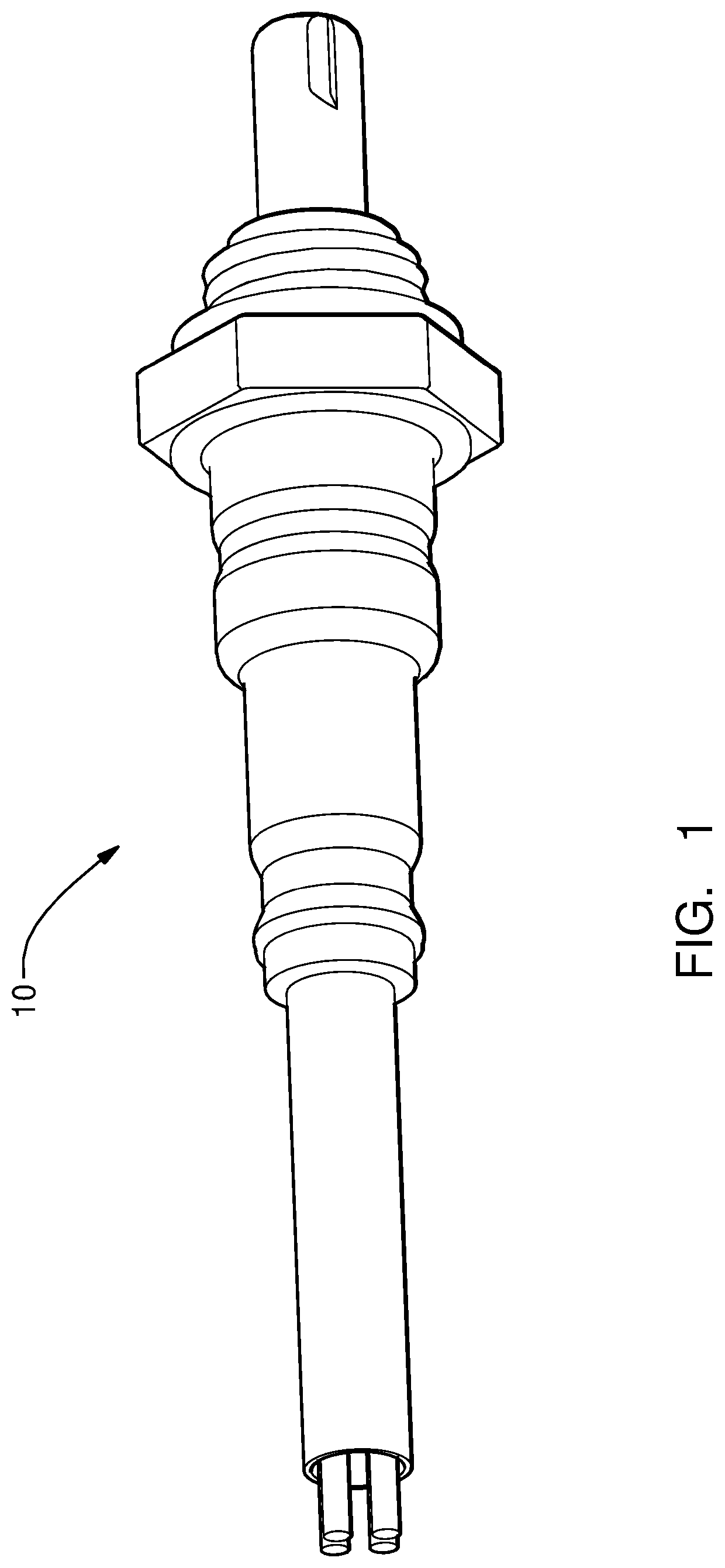
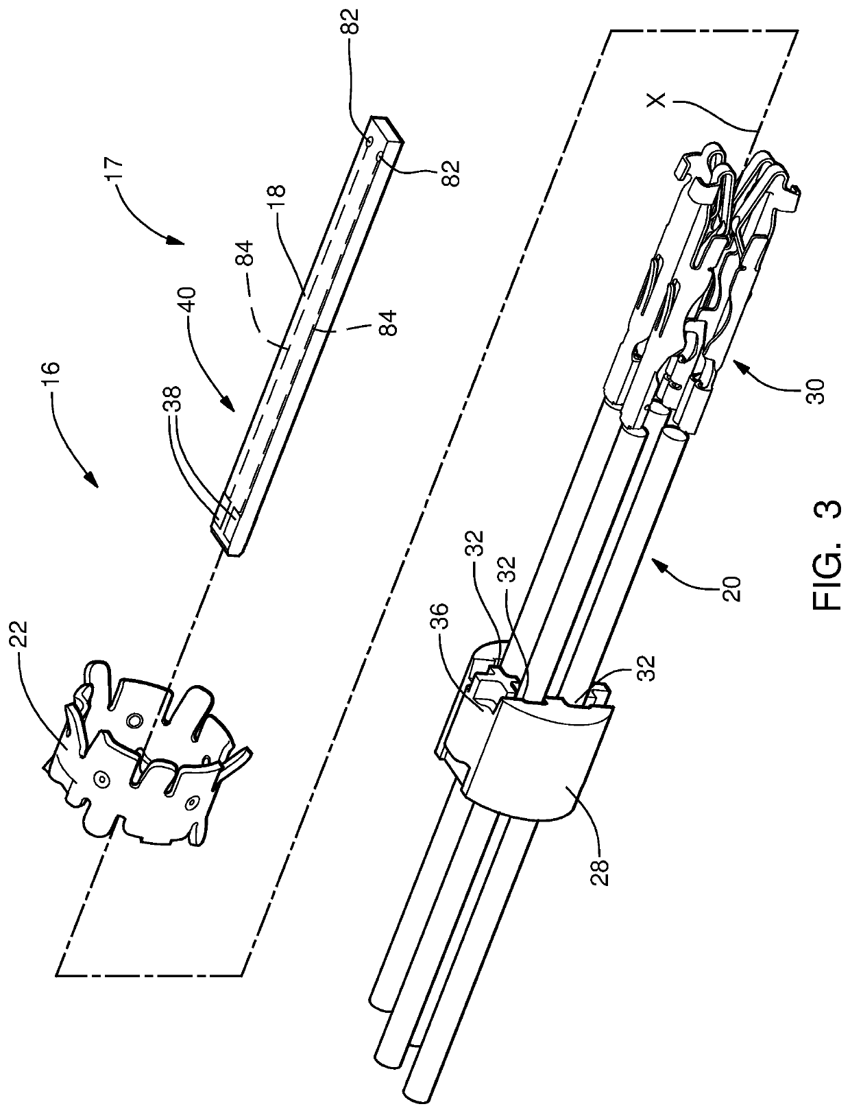
[0021]As illustrated in FIG. 1 an exhaust sensor 10 in accordance with the present disclosure is provided for sensing constituents of exhaust gases, for example exhaust gases produced by an internal combustion engine (not shown). As shown in FIG. 2, the exhaust sensor 10 includes a front housing 12, a rear housing 14, an electrical connector assembly 16 configured to interconnect a sensing element 17 with sensing element substrate 18, which contains the exhaust sensor circuitry, to a plurality of wire cables 20, a clip 22 configured to secure the electrical connector assembly 16 within the rear housing 14, a protective sleeve 24 to protect the wire cables 20, and a gasket 26 for mounting the front housing 12.

[0022]The details of the electrical connector assembly 16, hereinafter referred to as the connector 16 are shown in FIGS. 3 and 4. The connector 16 is made up of an insulative connector body 28 and at least one mating electrically conductive terminal 30 that, when fully assemble...


PUM

PropertyMeasurementUnit
thicknessaaaaaaaaaa
thicknessaaaaaaaaaa
normal forceaaaaaaaaaa

Abstract

An exhaust sensor includes a sensing element with a ceramic sensing element substrate and a sensing element terminal which is electrically conductive and which is supported by the ceramic sensing element substrate such that the sensing element is configured to sense constituents of exhaust gases when exposed thereto. The exhaust sensor also includes a mating terminal which is electrically conductive and which is in electrical communication with the sensing element terminal. The mating terminal has a base material and a clad material bonded to the base material such that the clad material contacts the sensing element terminal and such that the clad material is located between the sensing element terminal and the base material, thereby providing the electrical communication. The clad material is an alloy which is less than or equal to 20% iron, greater than or equal to 40% nickel, and greater than or equal to 13% chromium.

Description

TECHNICAL FIELD OF INVENTION[0001]The invention relates to exhaust sensors which are used to sense constituents of exhaust gases, more particularly to a terminal of the exhaust sensor which is suitable for high-temperature operation and which is robust to abrasion with a ceramic sensing element during manufacture.BACKGROUND OF INVENTION[0002]The automotive industry has used exhaust sensors in automotive vehicles for many years to sense the constituents in exhaust gases which are communicated through an exhaust conduit of an internal combustion engine. By way of non-limiting example only, exhaust sensors have been used to sense concentrations of oxygen, NOx, ammonia, and particulate matter. It is common for such exhaust gas sensors to include a sensing element which has a ceramic substrate which supports various electrodes and electrical leads which, when exposed to the exhaust gases, are able to produce an electrical signal that can be used to determine the concentration of a target...

Claims


Application Information

Patent Timeline
Patent Type & Authority Applications(United States)
IPC IPC(8): F01N11/00G01N27/407
CPCF01N11/002F01N2260/20F01N2560/025G01N27/407G01N27/4078G01N27/4062F01N2560/02Y02T10/40G03B17/14G03B17/56G03B17/02G02B27/646G02B7/14H04N23/00
Inventor NELSON, CHARLES S.
Owner DELPHI TECH IP LTD
Why Eureka
Try Eureka