
Ultra-high strength weathering steel for hot-stamping applications

Pending Publication Date: 2021-03-25
NUCOR CORP
View PDF5 Cites 0 Cited by
  • Summary
  • Abstract
  • Description
  • Claims
  • Application Information

AI Technical Summary

Benefits of technology

The patent text discusses how thin steel strips can be hot rolled to a desired thickness and then cooled. During this process, lubrication is used to reduce friction and provide a smoother surface finish. After cooling, the thin steel strips may undergo a pickling process to remove oxidation scale. However, this process can lead to defects known as separations, which can be several microns deep and affect the strength properties of the steel. The text also mentions that batch annealing can be used to reduce the strength of the steel.

Problems solved by technology

This etching may further cause a defect phenomenon to occur along the etched prior austenite grain boundaries and the resulting depressions.
Specifically, shifting the peritectic point away from the carbon region and / or increasing a transition temperature of the peritectic point of the composition appears to inhibit defects and results in a high strength martensitic steel sheet that is defect free.
Copper of the quantity in excess of 0.39% will have the opposite effect and will, instead, negatively impact the weathering characteristics when provided in excess of this quantity.
Moreover, prior austenitized steel compositions are known to produce an undesirable surface having scales, or oxidation, not suitable for the surface characteristics or properties required in hot-stamping applications.
It has been found that the light-gauge, ultra-high strength weathering steel sheet with strength properties greater than prior hot-stamped steel compositions (e.g. 300-600 MPa) and, thereby, may increase the wear on the punching equipment used during metal stamping.

Method used


Image

  • Ultra-high strength weathering steel for hot-stamping applications
  • Ultra-high strength weathering steel for hot-stamping applications
  • Ultra-high strength weathering steel for hot-stamping applications

Examples


Embodiment Construction

Example 2Example 3Example 4% C0.230.230.230.23% Si0.20.20.20.2% Mn111.21% P0.0190.0190.0190.019% S0.030.030.030.03% Cu0.450.40.380.4% Ni2.20.30.150.8% Cr30.20.151% Mo0.020.020.020.02% W0000% Ti0000% Co0000% N0.0050.0050.0050.005Corrosion10.1078656.165256.0091397.5208IndexMicro-MartensiticBainiticBainiticMartensitic +structureBainitic

[0144]As illustrated here, slowly cooling may additionally, or alternatively, produce a martensitic microstructure. Austenitizing, as a part of the hot-stamping application, will provide for the requisite austenite, regardless of whether it is a bainitie, martensitic, or martnsitic+bainitic microstructure. This material may then be relied on for hot stamping applications where the material is further heated and cooled during this hot stamping process to produce a martensitic microstructure that is present in a hot stamped product. The subsequent heating (e.g. austenitizing) and cooling (e.g. quenching) that occurs as a part of hot stamping application ad...


PUM

PropertyMeasurementUnit
Temperatureaaaaaaaaaa

Abstract

Disclosed herein is a light-gauge, ultra-high strength weathering steel sheet with a composition, material properties, and surface characteristics that make it suitable for hot-stamping applications and making hot-stamped products. Also disclosed herein is a high friction rolled carbon alloy steel strip free of prior austenite grain boundary depressions and having a smear pattern. Still further disclosed herein is a high friction rolled carbon alloy steel strip that has been surface homogenized to provide a thin cast steel strip free of a smear pattern.

Description

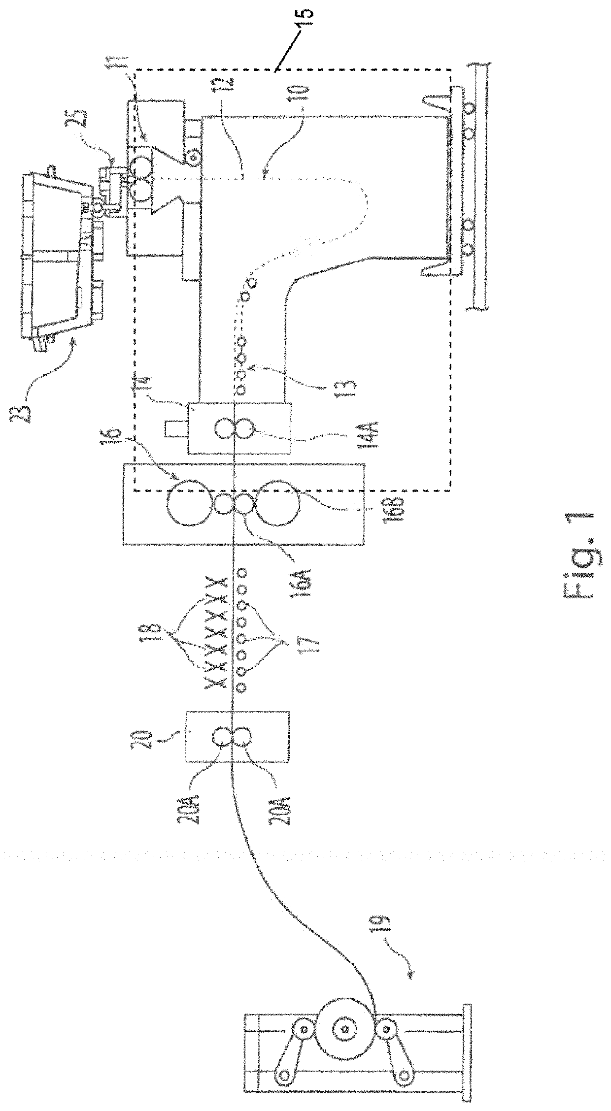
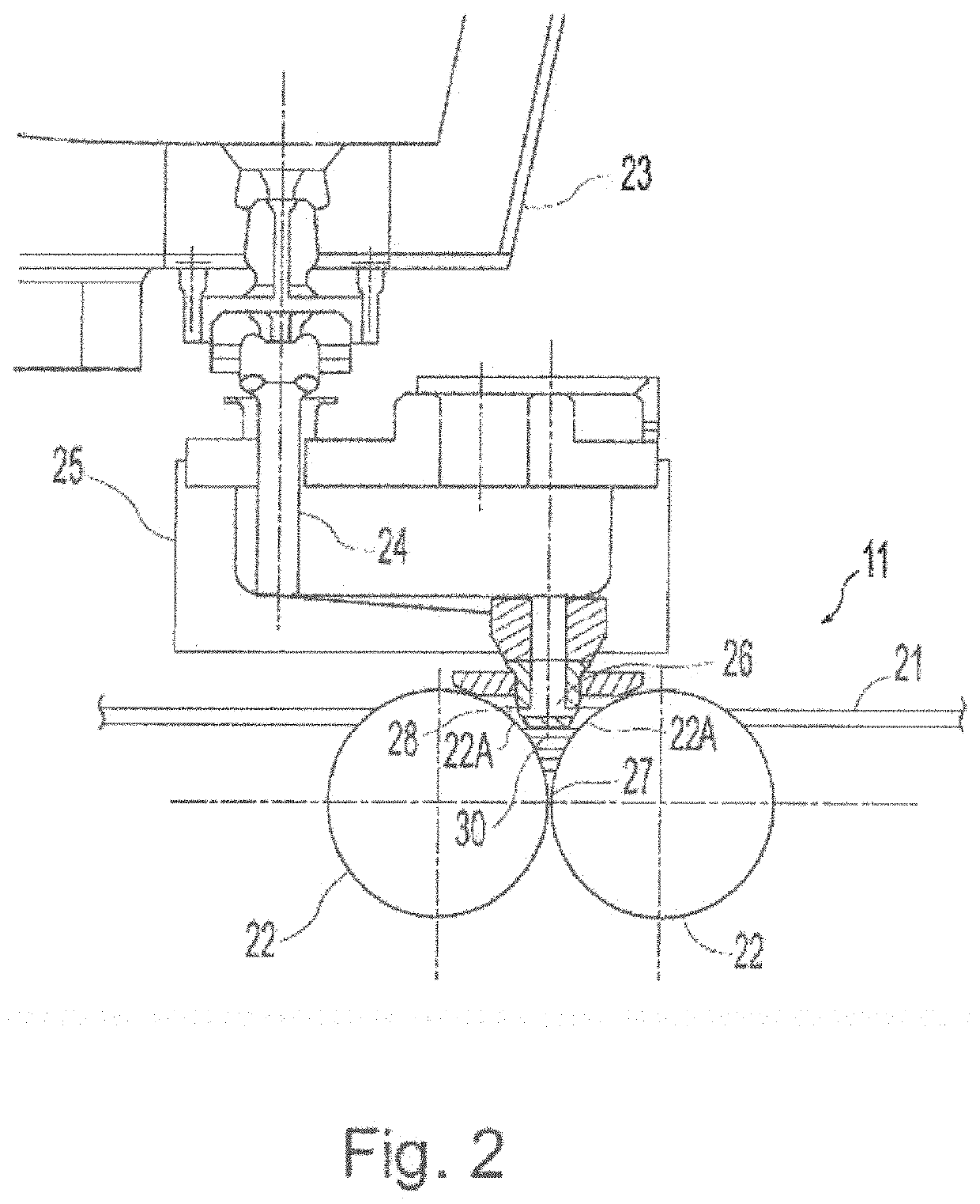
[0001]This patent application claims priority to and benefit of U.S. Provisional Application No. 62 / 902,825, filed Sep. 19, 2019, which is incorporated herein by reference.BACKGROUND AND SUMMARY[0002]This invention relates to thin cast steel strips, methods for producing a thin cast steel strip suitable for hot-stamping, and steel products made therefrom and thereby.[0003]In a twin roll caster, molten metal is introduced between a pair of counter-rotated, internally cooled casting rolls so that metal shells solidify on the moving roll surfaces, and are brought together at the nip between them to produce a solidified strip product, delivered downwardly from the nip between the casting rolls. The term “nip” is used herein to refer to the general region at which the casting rolls are closest together. The molten metal is poured from a ladle through a metal delivery system comprised of a tundish and a core nozzle located above the nip to form a casting pool of molten metal, supported on...

Claims


Application Information

Patent Timeline
IPC IPC(8): C21D9/56C21D9/48C21D8/02C21D6/00C22C38/48C22C38/46C22C38/42C22C38/04C22C38/06C22C38/02C22C38/00B21D22/02
CPCC21D9/563C21D2211/008C21D8/0205C21D8/0215C21D8/0226C21D6/004C21D6/005C21D6/008C22C38/48C22C38/46C22C38/42C22C38/04C22C38/06C22C38/02C22C38/002B21D22/022C21D2211/002C21D9/48C21D9/46C21D8/0263C21D9/52B21D5/08C22C38/58C22C38/16C22C38/08
Inventor MISHRA, KISHLAYKELLY, PAULWANG, TAO
Owner NUCOR CORP
Learn More