
Convolutional neural network evaluation of additive manufacturing images, and additive manufacturing system based thereon

a neural network and image technology, applied in the field of additive manufacturing, can solve the problems of slowed am's widespread adoption in critical industries, poor surface finish, and impede the acceptance of am for safety critical applications such as aerospace and medical applications

Active Publication Date: 2021-03-25
MOOG INC
View PDF0 Cites 5 Cited by
  • Summary
  • Abstract
  • Description
  • Claims
  • Application Information

AI Technical Summary

Benefits of technology

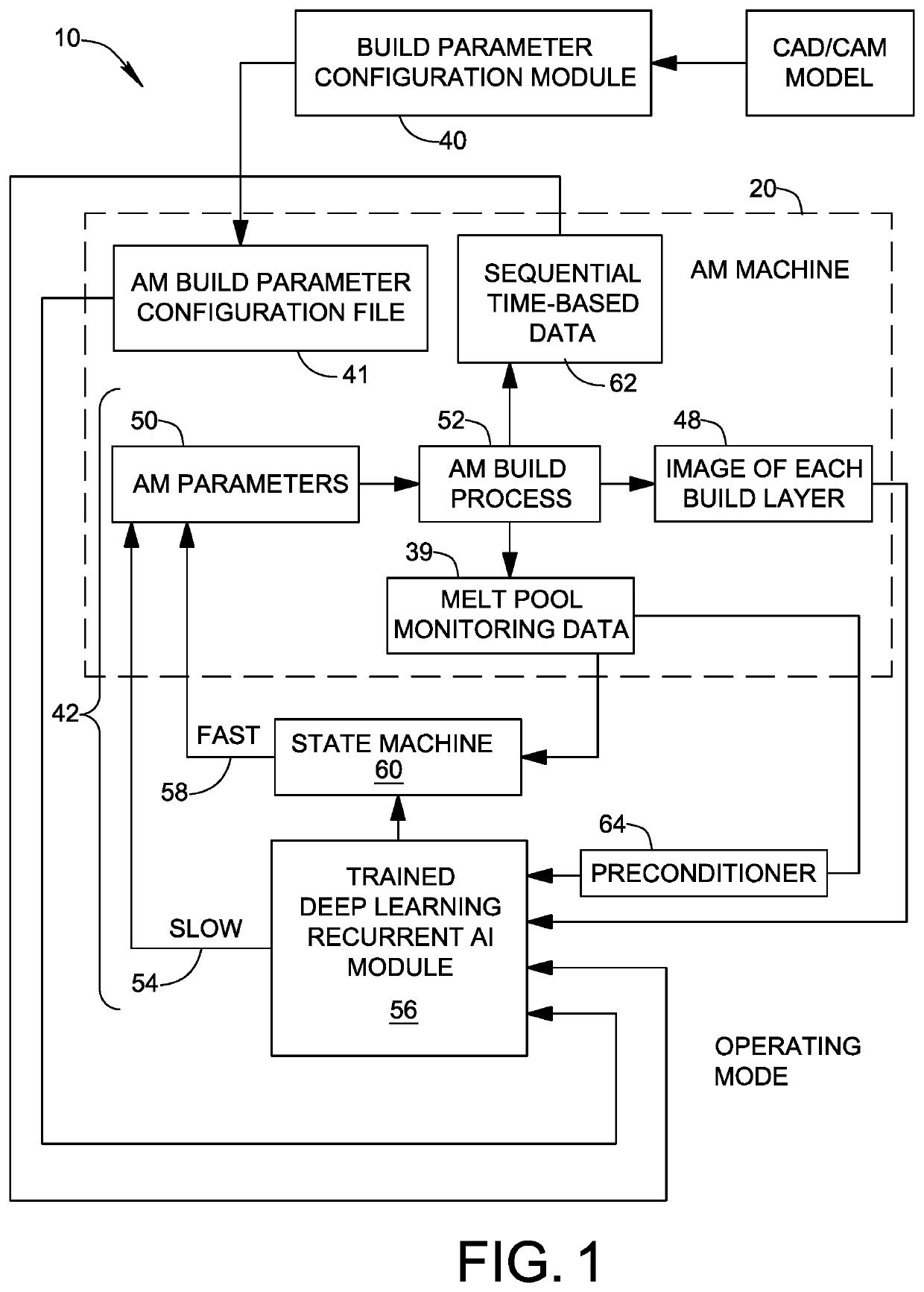
The present patent is about a system for building parts layer by layer in an AM machine. It includes a closed-loop control structure using a trained AI module and a state machine for adjusting the build parameters in real-time during the AM build process. The system also includes a melt-pool monitoring system and a build layer image sensor for acquiring real-time data and images of the part layers in-process. The trained AI module uses evaluations from two convolutional neural networks to learn and improve the build process. Overall, the system improves the accuracy and efficiency of AM building.

Problems solved by technology

While AM shows great promise for manufacturing parts that are difficult and / or time consuming to manufacture by traditional subtractive manufacturing, and for manufacturing parts “on demand” at remote locations where an AM machine is present, concerns about the quality of parts made by AM have slowed its widespread adoption in critical industries.
For example, parts made by AM sometimes exhibit porosity, voids, and poor surface finish, thus hampering acceptance of AM for safety critical applications such as aerospace and medical applications.
This places an added burden on quality control inspection of finished AM parts, especially for parts intended for safety critical applications such as medical devices and aircraft parts.
However, the publications lack any useful details or practical description of how to apply artificial intelligence to AM to improve the quality of finished parts.

Method used


Image

  • Convolutional neural network evaluation of additive manufacturing images, and additive manufacturing system based thereon
  • Convolutional neural network evaluation of additive manufacturing images, and additive manufacturing system based thereon
  • Convolutional neural network evaluation of additive manufacturing images, and additive manufacturing system based thereon

Examples


Embodiment Construction

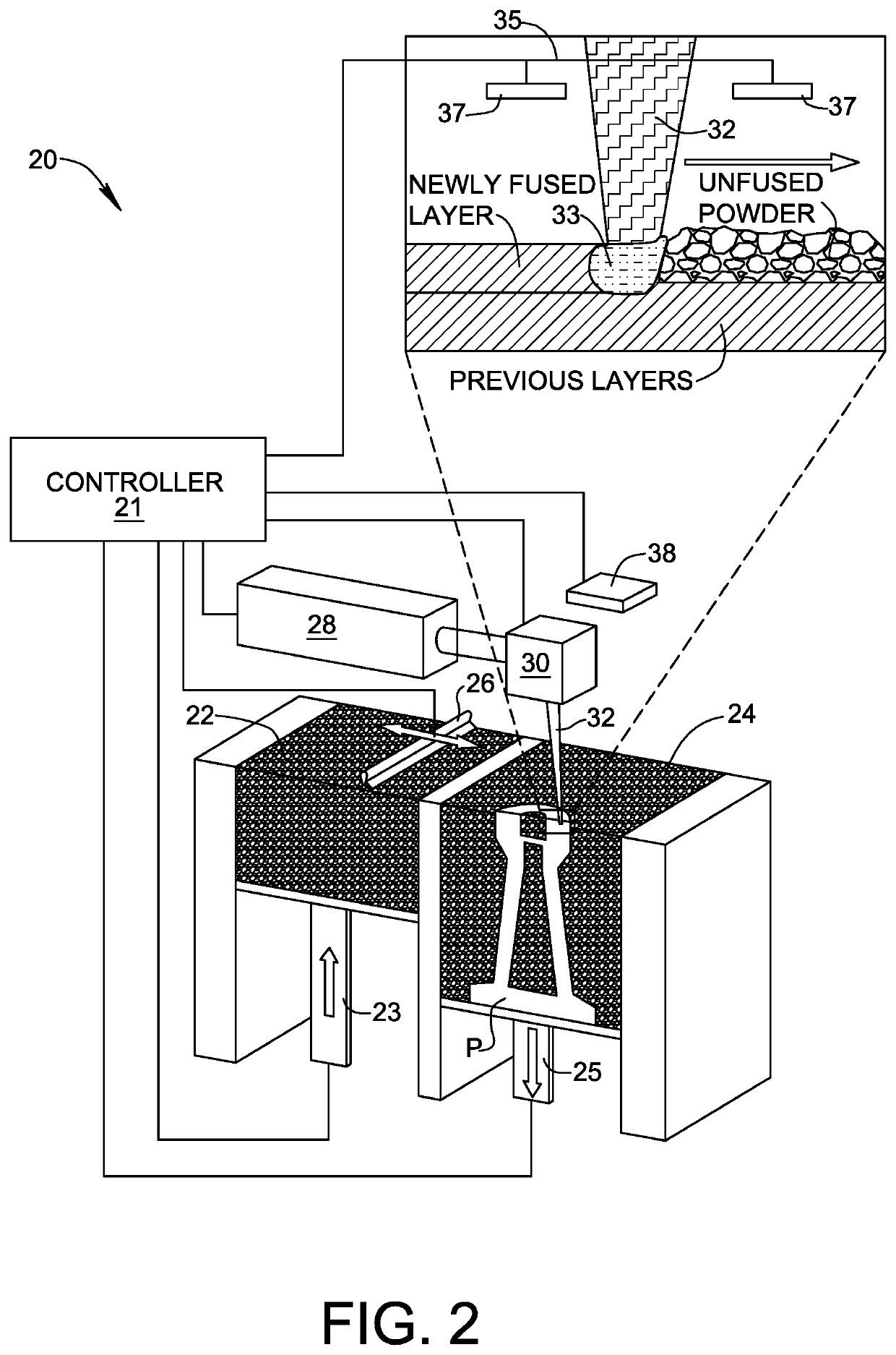
[0016]An AM system 10 formed in accordance with an embodiment of the present invention is shown in FIG. 1. AM system 10 comprises an AM machine 20, shown in greater detail in FIG. 2. AM machine 20 may be in the form of a laser powder bed machine of a type including a powder reservoir 22, a powder bed 24 in which a part P is built, and a powder scraper 26 for transferring a new layer of powder from powder reservoir 22 into powder bed 24. The elevation of powder reservoir is adjusted by means of a powder delivery actuator 23 and the elevation of powder bed 24 is adjusted by means of a fabrication actuator 25. AM machine 20 further includes an energy source in the form of a laser 28, and a scanner system 30 for redirecting and scanning a beam 32 from energy source 28 over each new layer of powder in powder bed 24 in a controlled manner to form part P. As will be understood, beam 30 interacts with powder layer in powder bed 24 and forms a trailing melt pool 33 which solidifies and fuses...


PUM

PropertyMeasurementUnit
Timeaaaaaaaaaa
Melting pointaaaaaaaaaa

Abstract

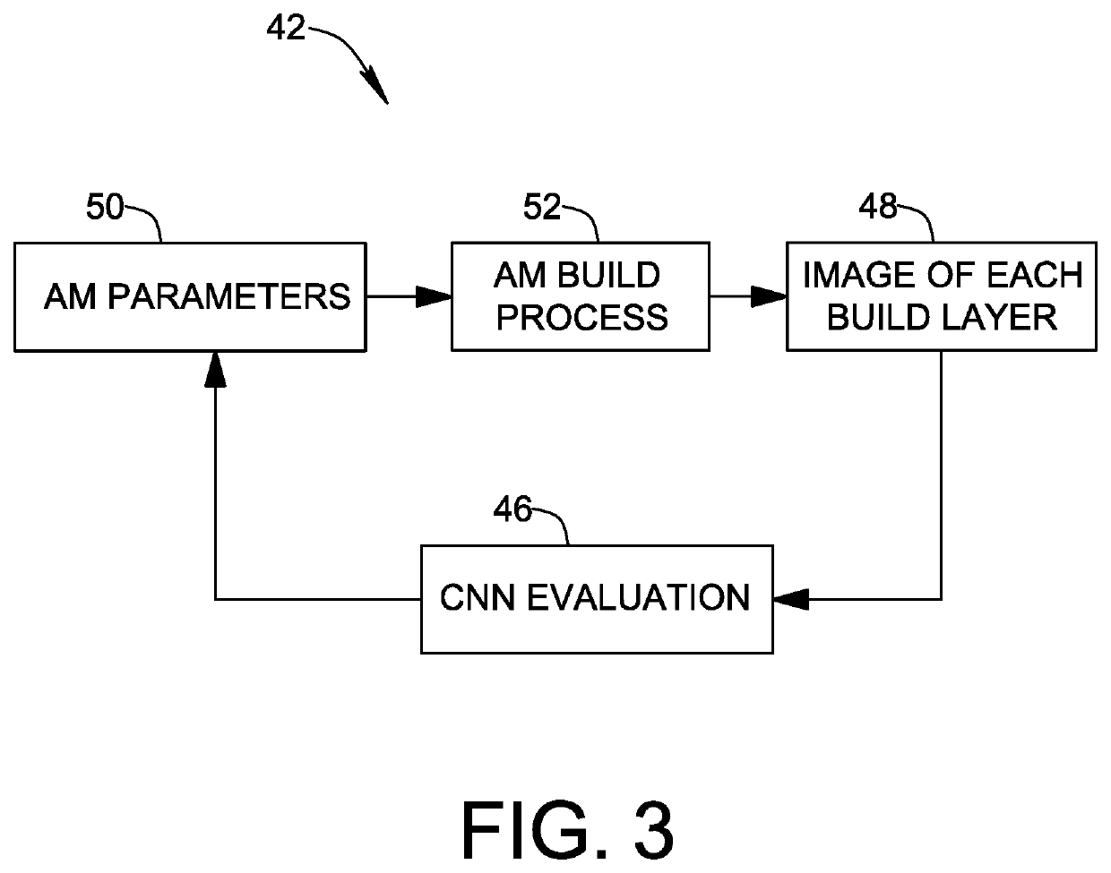
An additive manufacturing system uses a trained artificial intelligence module as part of a closed-loop control structure for adjusting the initial set of build parameters in-process to improve part quality. The closed-loop control structure includes a slow control loop taking into account in-process build layer images, and may include fast control loop taking into account melt pool monitoring data. The artificial intelligence module is trained using outputs from a plurality of convolutional neural networks (CNNs) tasked with evaluating build layer images captured in-process and images of finished parts captured post-process. The post process images may include two-dimensional images of sectioned finished parts and three-dimensional CAT scan images of finished parts.

Description

FIELD OF THE INVENTION[0001]The present invention relates to the field of additive manufacturing (AM).BACKGROUND OF THE INVENTION[0002]AM machines are useful in building finished parts according to a layer-by-layer build process. For example, laser powder bed fusion AM machines use either a laser or an electron beam to melt and fuse powder material. Powder bed fusion processes involve spreading thin layers of powder material over previous layers using a roller or a blade, and scanning the laser or electron beam in a controlled manner over the powder layer to form the layer according to a desired geometry of the part. A geometric computer model of the part is converted to an AM build parameter file in which various control parameters of the AM machine are defined for controlling the scanning and fusion operations for each build layer.[0003]While AM shows great promise for manufacturing parts that are difficult and / or time consuming to manufacture by traditional subtractive manufactur...

Claims


Application Information

Patent Timeline
IPC IPC(8): G05B19/4099B29C64/393B33Y30/00B33Y50/02G06N20/00
CPCG05B19/4099B29C64/393G05B2219/49023B33Y50/02G06N20/00B33Y30/00B29C64/153Y02P10/25B22F10/28B22F12/90B22F10/85B22F2203/03B33Y50/00B22F2999/00G06N3/08G05B2219/49007G05B13/027G06N3/044G06N3/045B22F10/30
Inventor GUERRIER, PAULBAGGS, GEORGE
Owner MOOG INC
Learn More