
Minimally invasive hip arthroplasty techniques and apparatus

a hip arthroplasty and minimally invasive technology, applied in the field of minimally invasive hip arthroplasty techniques and equipment, can solve the problems of difficulty in providing sufficient force with such equipment or obtaining correct alignment, and achieve the effect of increasing component placement accuracy and minimizing trauma

Active Publication Date: 2021-04-01
PMSW RES PTY LTD
View PDF21 Cites 2 Cited by
  • Summary
  • Abstract
  • Description
  • Claims
  • Application Information

AI Technical Summary

Benefits of technology

The patent describes minimally invasive techniques for hip replacement surgery that aim to reduce trauma and improve component placement accuracy. The techniques involve using a smaller diameter reaming rod and an intramedullary broach that references the non-variant axis of the femur and bore axis of the broach. The method may also counter drive rod rotation eccentricities that could fracture the femoral neck. The bore has a cross-section that allows for adjustment of the reaming rod aim through the femoral neck and head, and does not require a large incision. Overall, these techniques may improve the accuracy and efficiency of hip replacement surgery.

Problems solved by technology

However, it is difficult to provide sufficient force with such apparatus or to obtain correct alignment.

Method used


Image

  • Minimally invasive hip arthroplasty techniques and apparatus
  • Minimally invasive hip arthroplasty techniques and apparatus
  • Minimally invasive hip arthroplasty techniques and apparatus

Examples


Embodiment Construction

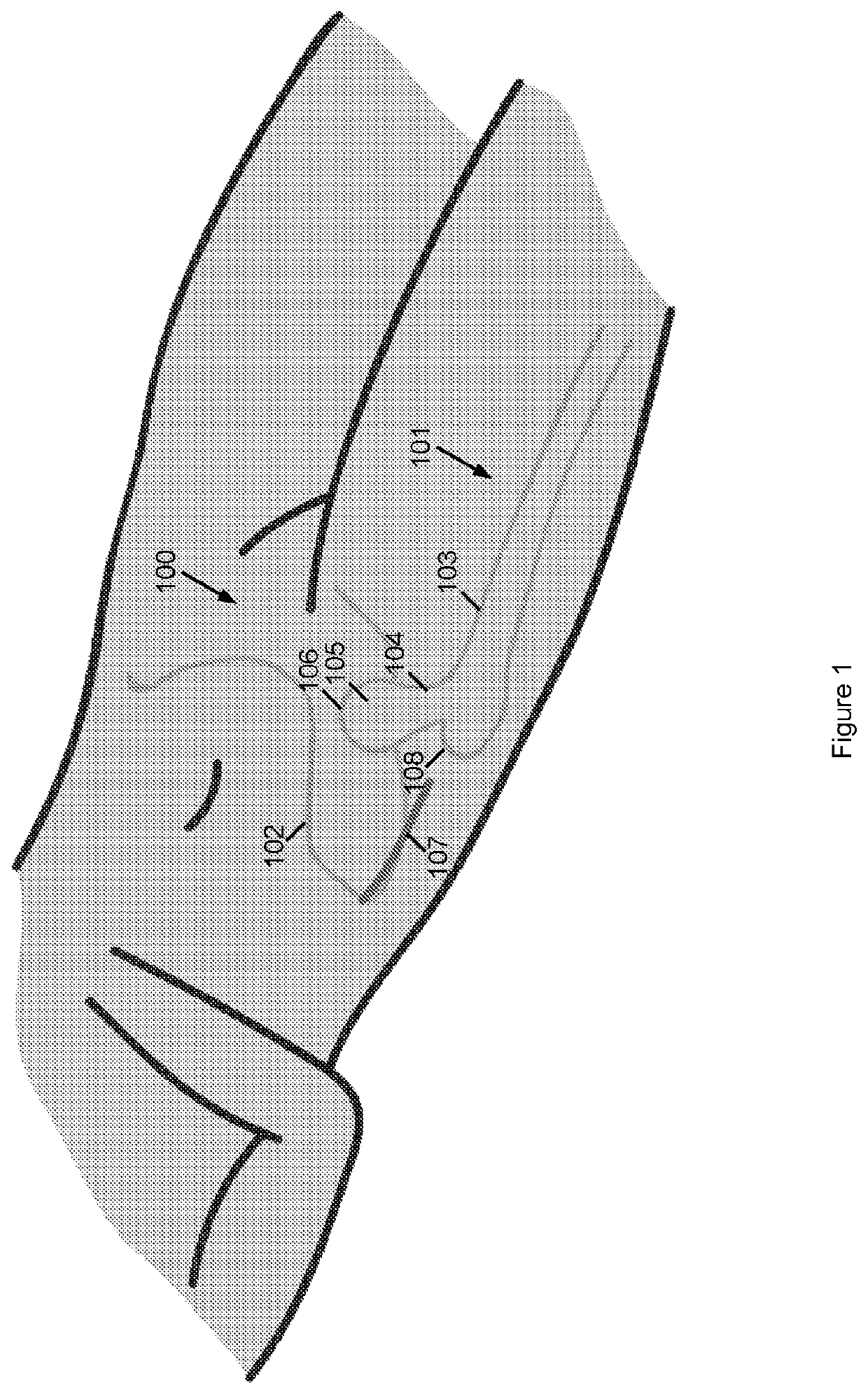
[0110]FIGS. 1-25 illustrate hip joint 100 arthroplasty techniques. As can be seen from FIG. 1, the hip joint 100 comprises a femur 101 having a femoral shaft 103, neck 104, head 105 and greater trochanter 108. The femur 101 locates adjacent a pelvis 102 having an acetabulum 106 formed therein.

[0111]The hip joint 100 may be accessed via a superior incision 107 in the general location shown in FIG. 1.

[0112]Orientation will be described hereafter with reference to superior being towards the head and inferior being towards the feet of the patient. Furthermore, the lateral and derivatives thereof refer to out away from the side of the body in the dorsal planes and medial and derivatives thereof in towards the side of the body in this plane. Lateromedially refers to in a direction from lateral to medial and mediolaterally refers to the opposite direction.

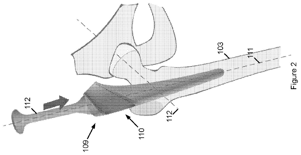
[0113]Referring to FIG. 2, the method comprises the insertion of an elongate femoral broach 109 into the medullary cavity of the shaft 1...


PUM


Abstract

A minimally invasive hip arthroplasty technique involves intramedullary insertion of an elongate femoral broach into a femur. The broach has a superior lateromedial transverse bore. A reaming rod is then located through the transverse bore and the neck of the femur. A cutting head is coupled to a distal end of the reaming rod via an incision. An orthogonal drive arm of an arthroplasty jig may also be inserted behind the cutting head to press the cutting head to ream the acetabulum while the reaming rod rotates the cutting head.

Description

FIELD OF THE INVENTION[0001]This invention relates generally to minimally invasive hip arthroplasty techniques and apparatus. More particularly, this invention relates to techniques and apparatus for joint arthroplasty which minimises substantial retraction for femoral dislocation and associated iatrogenic soft tissue trauma as is associated with certain prior art arrangements.BACKGROUND OF THE INVENTION[0002]There are numerous ways to perform a joint arthroplasty, but which all share the same goal of replacement of the dysfunctional arthritic joint and replacing with materials that preserve joint function. Hip arthroplasty treatments or procedures are intended to provide a pain-free weight bearing joint whose motion replicates the native hip joint.[0003]Arthroplasty procedures of the hip joint specifically target disease of the femoral head (ball portion) and acetabulum (socket portion). Traditional total hip replacement surgery excises the femoral head and a portion of the femoral...

Claims


Application Information

Patent Timeline
IPC IPC(8): A61B17/17A61B17/16A61B17/00A61B17/92A61B17/02A61F2/46
CPCA61B17/1746A61F2002/4635A61B17/1668A61B17/175A61B17/00234A61B17/164A61B17/1642A61B17/921A61B17/025A61F2/4684A61F2/4607A61B2017/00353A61B2017/0275A61B2017/922A61B17/1666A61B17/1742A61B17/1659A61B17/1735A61F2/36A61F2/34A61B2017/00469A61B17/1631A61B17/8875A61F2/32A61B17/16A61B17/56A61F2/46
Inventor WALKER, PETER
Owner PMSW RES PTY LTD
Learn More