Endothermic reactions heated by resistance heating

a technology of resistance heating and endothermic reactions, applied in the field of reactor systems, can solve the problems of endothermic reactions, slow heat transfer by conventional heat transfer, convection and/or radiation heating, etc., and achieve the effects of facilitating steam reforming reaction, reducing the overall emission of carbon dioxide and other emissions detrimental to the climate, and facilitating the steam reforming reaction

Pending Publication Date: 2021-04-22
HALDOR TOPSOE AS
View PDF0 Cites 11 Cited by
  • Summary
  • Abstract
  • Description
  • Claims
  • Application Information

AI Technical Summary

Benefits of technology

[0007]An advantage of the invention is that the overall emission of carbon dioxide and other emissions detrimental to the climate may be reduced considerably, in particular if the power used in the reactor system is from renewable energy resources.
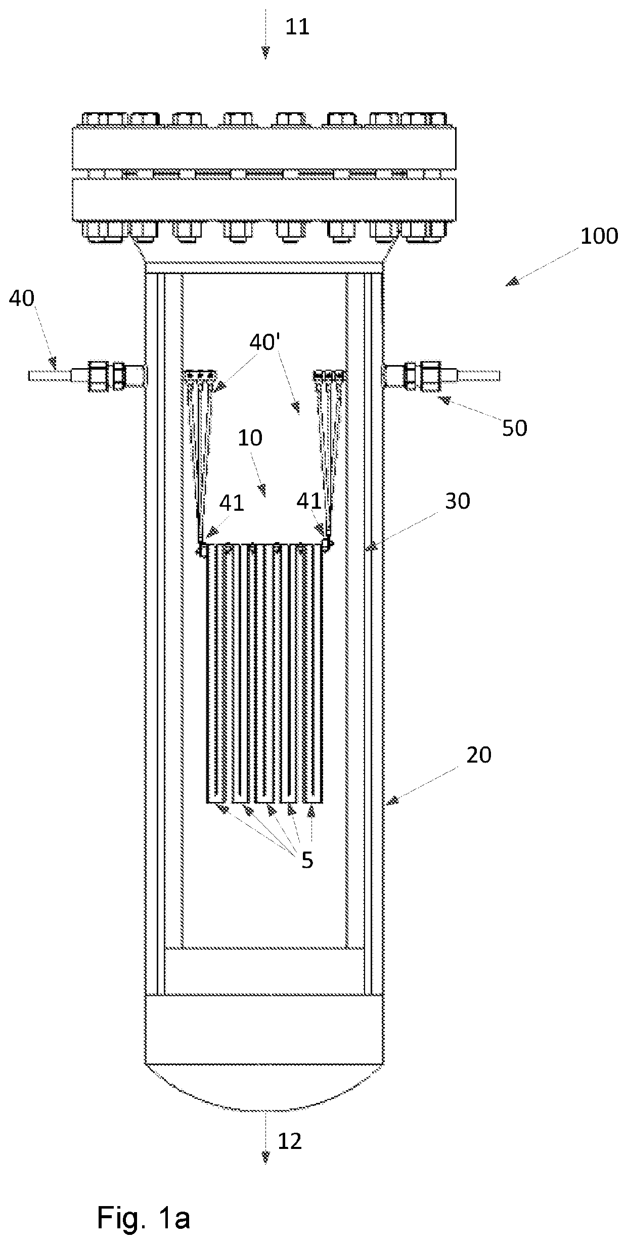
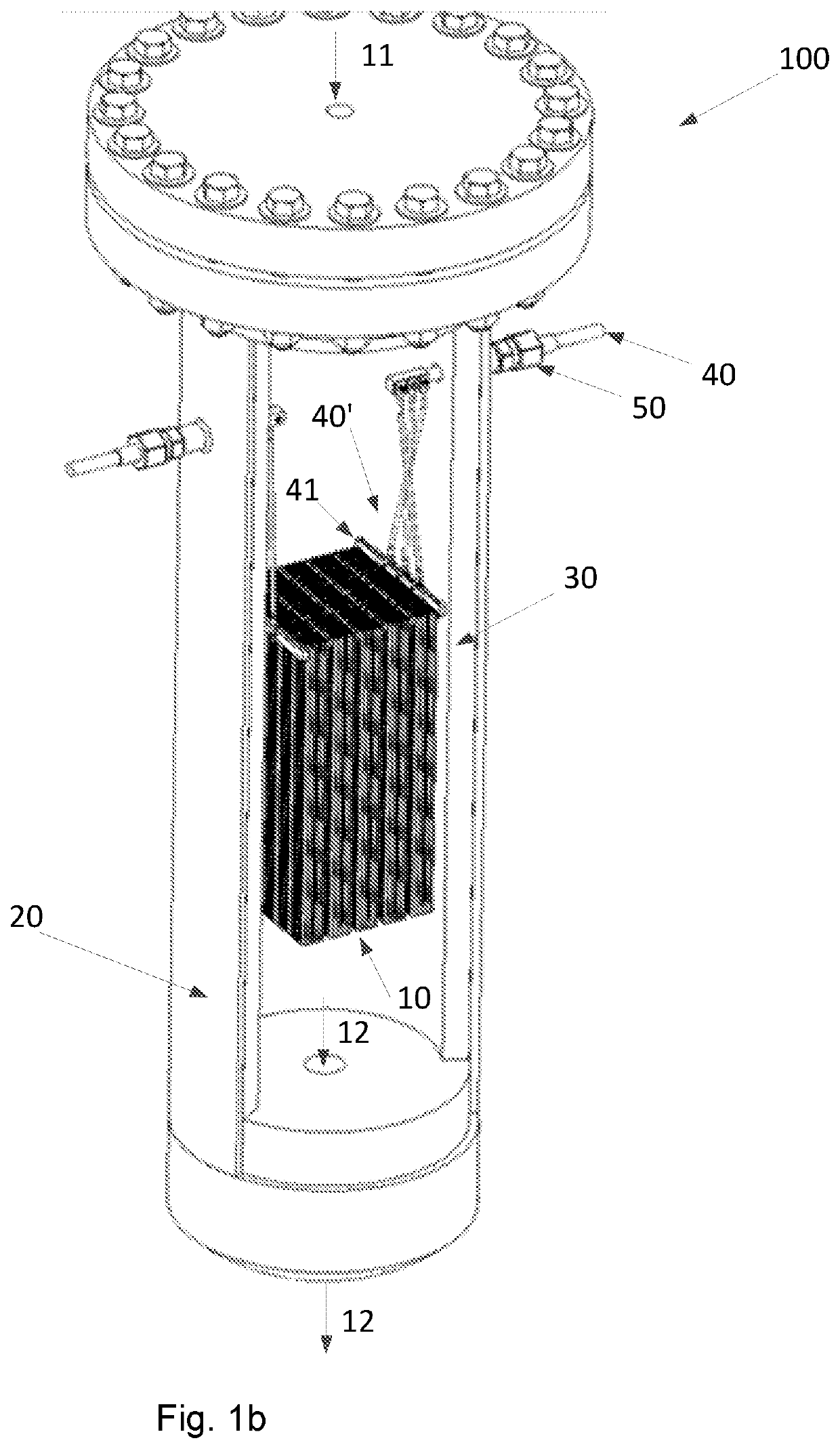
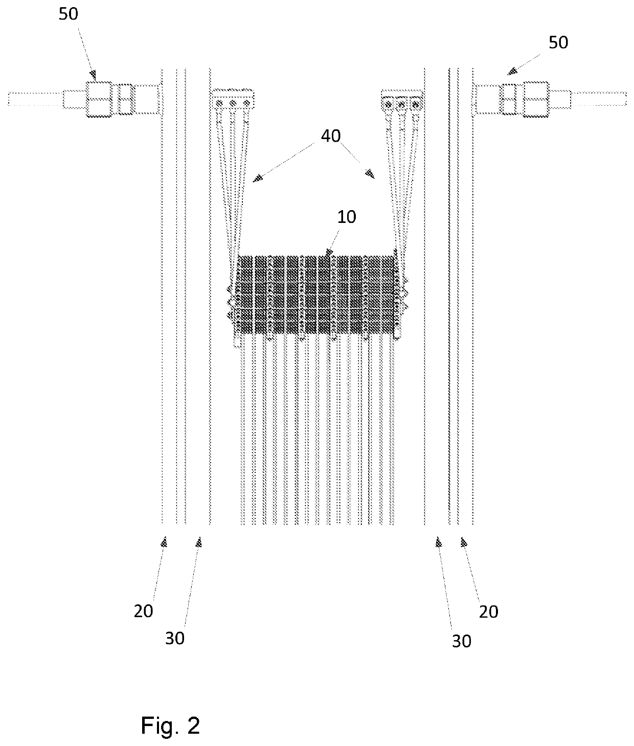
[0008]Embodiments of the invention generally relate to a reactor system for carrying out an endothermic reaction of a feed gas, the reactor system comprising:
[0009]a structured catalyst arranged for catalyzing the endothermic reaction of a feed gas, where the structured catalyst comprises a macroscopic structure of electrically conductive material, where the macroscopic structure supports a ceramic coating and
[0014]at least two conductors electrically connected to said structured catalyst and to an electrical power supply placed outside the pressure shell, wherein the electrical power supply is dimensioned to heat at least part of the structured catalyst to a temperature of at least 200° C. by passing an electrical current through the electrically conductive material.
[0015]The layout of the reactor system allows for feeding a pressurized feed gas to the reactor system at an inlet and directing this gas into the pressure shell of the reactor system. Inside the pressure shell, a configuration of heat insulation layers and inert material is arranged to direct the feed gas through the structured catalyst where it will be in contact with the catalyst material, where the catalytically active material will facilitate the steam reforming reaction. Additionally, the heating of the structured catalyst will supply the required heat for the endothermic reaction. Th

Problems solved by technology

Endothermic reactions will often be challenged by how efficient heat can be transferred to the reactive zone of the catalyst bed within a reactor unit

Method used


Image

  • Endothermic reactions heated by resistance heating
  • Endothermic reactions heated by resistance heating
  • Endothermic reactions heated by resistance heating

Examples


example 2

[0149]An example calculation of the process of the invention is given in Table 2 below. A hydrocarbon feed stream comprising i.a. a hydrocarbon gas, hydrogen and steam is fed to the reactor system of the invention. The feed stream entering the reactor system is pressurized to a pressure of 28 kg / cm2·g and has a temperature of 500° C. Inside the reactor system, a structured catalyst in the form of 1 macroscopic structure having a square cross section is placed which has a size of 0.4 times 0.4 times 0.35 meter. The structured catalyst additionally has 10000 channels with a square cross section having a side or edge length of 0.32 cm. The structured catalyst has slits parallel to the longitudinal direction thereof, so that clusters of 5 times 5 channels are formed. The clusters are individually insulated from the neighboring cluster, except from the ends, so that the current path through the structured catalyst is a zigzag path. A current of 200 A and a voltage of ca. 500 V are applie...

example 3

[0152]An example calculation of the process of the invention is given in Table 3 below. A hydrocarbon feed stream comprising i.a. a hydrocarbon gas, hydrogen and steam is fed to the reactor system of the invention. The feed stream entering the reactor system is pressurized to a pressure of 97 bar, viz. 97 kg / cm2·g and has a temperature of 500° C.

[0153]Inside the reactor system, a structured catalyst comprising nine macroscopic structures having a square cross section are placed in an array and each macroscopic structure has a size of 0.53 times 0.53 times 2.3 meter. Each macroscopic structure additionally has 17778 channels with a square cross section having a side or edge length of 0.32 cm. Each macroscopic structure has slits parallel to the longitudinal direction thereof, so that clusters of 5 times 5 channels are formed. The clusters are individually insulated from the neighboring cluster, except from the ends so that the current path through the structured catalyst is a zigzag ...

example 4

[0157]An example calculation of the process of the invention is given in Table 3 below. A hydrocarbon feed stream comprising i.a. a hydrocarbon gas, hydrogen and steam is fed to the reactor system of the invention. The feed stream entering the reactor system is pressurized to a pressure of 28 bar, viz. 28 kg / cm2·g and has a temperature of 500° C.

[0158]Inside the reactor system, structured catalyst comprising 25 macroscopic structures having a square cross section are placed in an array and each macroscopic structure has a size of 0.24 times 0.24 times 1.8 meter. Each macroscopic structure additionally has 4702 channels with a square cross section having a side or edge length of 0.33 cm in length. Each macroscopic structure has slits parallel to the longitudinal direction thereof, so that clusters of 10 times 10 channels are formed. The clusters are individually insulated from the neighboring cluster, except from the ends, so that the current path through the structured catalyst is a...


PUM

PropertyMeasurementUnit
Temperatureaaaaaaaaaa

Abstract

A reactor system for carrying out an endothermic reaction of a feed gas, including: a structured catalyst arranged for catalyzing the endothermic reaction of a feed gas, the structured catalyst including a macroscopic structure of electrically conductive material, the macroscopic structure supporting a ceramic coating, wherein the ceramic coating supports a catalytically active material; a pressure shell housing the structured catalyst; heat insulation layer between the structured catalyst and the pressure shell; at least two conductors electrically connected to the electrically conductive material and to an electrical power supply placed outside the pressure shell, wherein the electrical power supply is dimensioned to heat at least part of said structured catalyst to a temperature of at least 200° C. by passing an electrical current through the electrically conductive material. Also, a process for performing an endothermic reaction of a feed gas.

Description

FIELD OF THE INVENTION[0001]Embodiments of the invention relate to a reactor system and a process for carrying out steam reforming of a feed gas comprising hydrocarbons where the heat for the endothermic reaction is provided by resistance heating.BACKGROUND[0002]Endothermic reactions will often be challenged by how efficient heat can be transferred to the reactive zone of the catalyst bed within a reactor unit. Conventional heat transfer by convection, conduction and / or radiation heating can be slow and will often meet large resistance in many configurations. This challenge can be illustrated with the tubular reformer in a steam reforming plant, which practically can be considered as a large heat exchanger with heat transfer as the rate limiting step. The temperature at the innermost part of the tubes of the tubular reformer is somewhat lower than the temperature outside the tubes due to the heat transfer rate through the walls of the tube and to the catalyst within the tubes as wel...

Claims


Application Information

Patent Timeline
IPC IPC(8): B01J12/00B01J19/24B01J19/00C01B3/38C01B3/04C01C3/02C07C5/327C07C5/393
CPCB01J12/007C01B2203/1023B01J19/0013C01B3/384C01B3/047C01C3/0208C07C5/327C07C5/393B01J2219/00155B01J2219/00135B01J2219/0004C01B2203/0233C01B2203/085C01B2203/1235B01J19/2485C07C5/333C01B3/22C01B3/40C01B2203/0883C01B2203/1058C01B2203/1264C01B2203/141C01C3/02B01J15/005C07C2523/42C07C2523/62C07C2523/14C10G35/06C10G47/02B01J2219/00162B01J19/32B01J8/0257B01J2219/2407B01J2219/2416B01J2219/2428B01J2219/2432B01J2219/2438B01J2219/2445B01J2219/2443Y02E60/36C07C11/06
Inventor MORTENSEN, PETER MØLGAARDKLEIN, ROBERTAASBERG-PETERSEN, KIM
Owner HALDOR TOPSOE AS
Why Eureka
Try Eureka