Method and apparatus for in-situ removal of per- and poly-fluoroalkyl substances

Pending Publication Date: 2021-05-06
KERFOOT TECH
View PDF7 Cites 3 Cited by
  • Summary
  • Abstract
  • Description
  • Claims
  • Application Information

AI Technical Summary

Benefits of technology

[0026]In other embodiments, the treatment method includes injecting gaseous ozone into the groundwater or soil formation at a plurality of points along a vertical axis. Still further, fine ozone bubbles can be released at the base of a double-screened well such that, as the ozone bubbles travel vertically due to buoyancy, they lift the water towards an upper well screen, with the water movement in the soil being downward from the top of the upper well screen. The fine bubbles enter the upper screen area with the water flow such that the rate of removal of aqueous PFAS is greatest within the well and secondly in the lower portions of the soil. As the ozone bubbles change depth, the pressure decreases on them allowing some expansion, and they rise faster outside the well casing. Liquid flow (e.g., either peroxide or hydroxide) can be delivered to a lower laminar point under the screened casing to coat the bubbles or change the pH to enhance reaction with PFAS compounds. A mineral catalyst can be placed around the bubbling porous screen of the bubble generator to further enhance re

Problems solved by technology

The toxicity and bioaccumulation potential of PFOS and PFOA, however, indicate a cause for concern.
Locations for disposal of leachate are increasingly limited.
Notably, landfills are no longer accepting leachate with PFAS compounds for disposal.
Additionally, incineration of leachate with PFAS comp

Method used


Image

  • Method and apparatus for in-situ removal of per- and poly-fluoroalkyl substances
  • Method and apparatus for in-situ removal of per- and poly-fluoroalkyl substances
  • Method and apparatus for in-situ removal of per- and poly-fluoroalkyl substances

Examples


Embodiment Construction

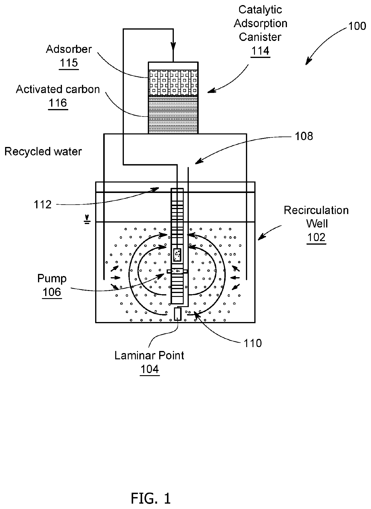
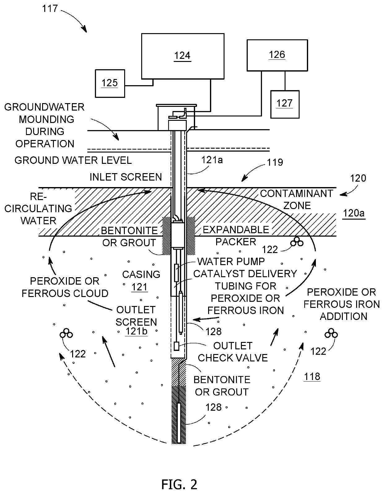
[0047]FIG. 1 shows an embodiment of a system for removing PFAS contaminants from a groundwater or soil formation in accordance with the present invention. In FIG. 1, the system is generally designated as reference numeral 100. For clarity of illustration, some control mechanisms are not shown, though they are of the type and design generally understood in the art. A recirculation well (generally designated as reference numeral 102 and described in more detail in connection with FIG. 2) is shown inserted into an area of contamination. A laminar point diffuser 104, generally located at the bottom of the well 102, receives gas and ozone from a control mechanism (not shown) and generates bubbles, preferably fine nano- or micro-bubbles) which are introduced into the soil and groundwater surrounding the recirculation well. A second diffuser (not shown) is located inside the recirculation well 102. A pump 106 inside the well 102 takes groundwater from an inlet 108 in an upper portion of th...


PUM


Abstract

Apparatus and method for removing PFAS compounds from contaminated groundwater or soil includes a well having diffusers for injecting gaseous ozone as bubbles into water in the groundwater or soil formation, a catalytic adsorption canister having an inlet and at least one outlet coupled to the groundwater or soil formation; a control mechanism for supplying gaseous ozone to the well and the catalytic adsorption canister, and a pump in the well, the pump having an inlet for receiving groundwater from an upper portion of the well, a first outlet coupled to a lower portion of the well and a second outlet coupled to the inlet of the catalytic adsorption canister. The catalytic adsorption canister, which can also be used as a stand-alone system for ex-situ treatment of groundwater, includes a mineral catalyst to adsorb PFAS compounds, which are thereafter mineralized and decomposed by exposure of ozone bubbles.

Description

CROSS-REFERENCE TO RELATED APPLICATION[0001]This application claims the benefit of U.S. Provisional Application No. 62 / 931,510, filed Nov. 6, 2019, which is incorporated herein by reference in its entirety.TECHNICAL FIELD OF THE INVENTION[0002]The present invention generally relates to methods and apparatus for soil and groundwater treatment. More particularly, the present invention relates to methods and apparatus for reducing or eliminating per- and poly-fluoroalkyl substances (PFASs) concentrations in soil and groundwater.BACKGROUND OF THE INVENTION[0003]Perfluoroalkyl compounds such as PFOS (perfluoroalkyl sulfonate) and PFOA (perfluoroalkyl octanoic acid) are human-made substances, not naturally found in the environment, which do not hydrolyze, photolyze, or biodegrade in groundwater or soil. These compounds have been used as surface-active agents in a variety of products such as fire-fighting foams, coating additives and cleaning products. The toxicity and bioaccumulation pote...

Claims


Application Information

Patent Timeline
IPC IPC(8): C02F1/72C02F1/00C02F1/78B09C1/08B09C1/00C02F1/28
CPCC02F1/725C02F1/008C02F1/78C02F1/722C02F2103/06B09C1/002C02F1/281C02F1/283B09C1/08B09C2101/00C02F2101/36C02F1/28
Inventor KERFOOT, WILLIAM B.
Owner KERFOOT TECH
Why Eureka
Try Eureka