Optical filter having dual polarization

a technology of optical sensors and polarization, applied in the direction of polarising elements, instruments, manufacturing tools, etc., can solve the problems of impaired sensing and control systems, and achieve the effects of accurate control of the fabrication process, accurate sensing of process parameters, and increased snr performance of optical sensors

Pending Publication Date: 2021-05-13
SIGMA LAB OF ARIZONA
View PDF4 Cites 1 Cited by
  • Summary
  • Abstract
  • Description
  • Claims
  • Application Information

AI Technical Summary

Benefits of technology

[0009]Numerous benefits are achieved by way of the present invention over conventional techniques. For example, embodiments of the present invention provide the ability to increase SNR performance of optical sensors. The improved SNR enables more accurate sensing of the process parameters and more accurate control of the fabrication process.

Problems solved by technology

During the manufacturing process optical noise is generated in the form of spurious light emissions and mixed light signal polarizations resulting in impaired fidelity of the sensing and control systems.

Method used


Image

  • Optical filter having dual polarization
  • Optical filter having dual polarization
  • Optical filter having dual polarization

Examples


Embodiment Construction

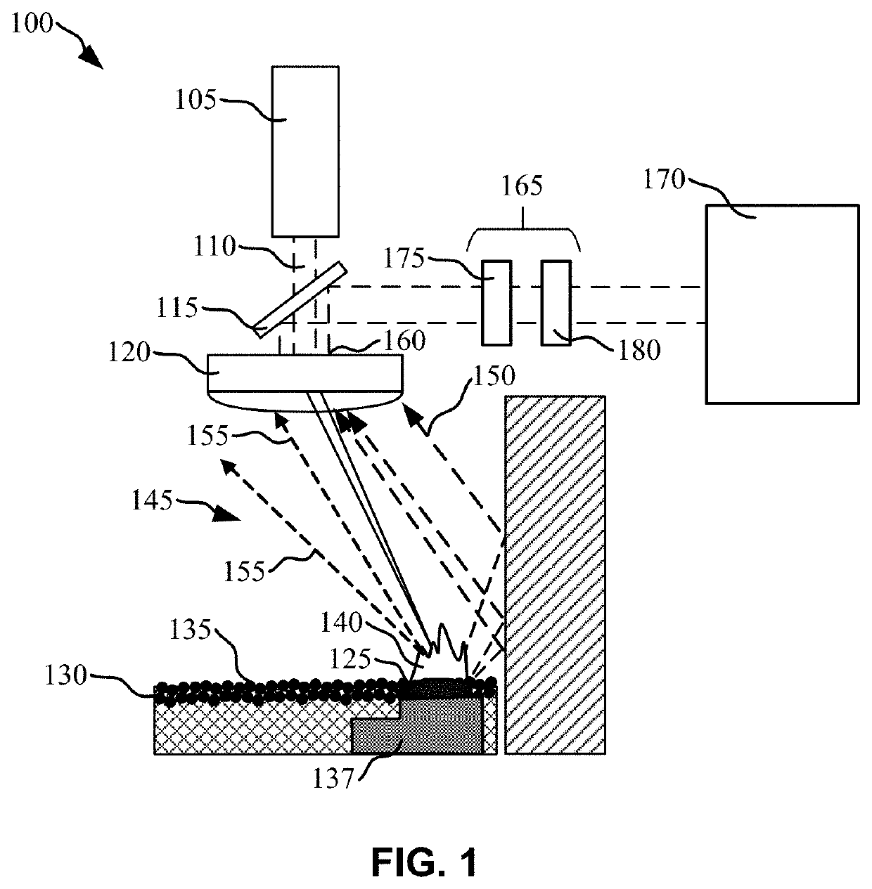
[0015]Techniques disclosed herein relate generally to systems that receive and / or process optical signals. More specifically, techniques disclosed herein relate to the use of a dual polarization optical filter to improve the signal to noise ratio (SNR) of optical signals. In some instances, embodiments of the disclosure are particularly well suited for use with additive manufacturing systems because of the relatively high noise level and the stochastic nature of the optical signals, as described in more detail below.

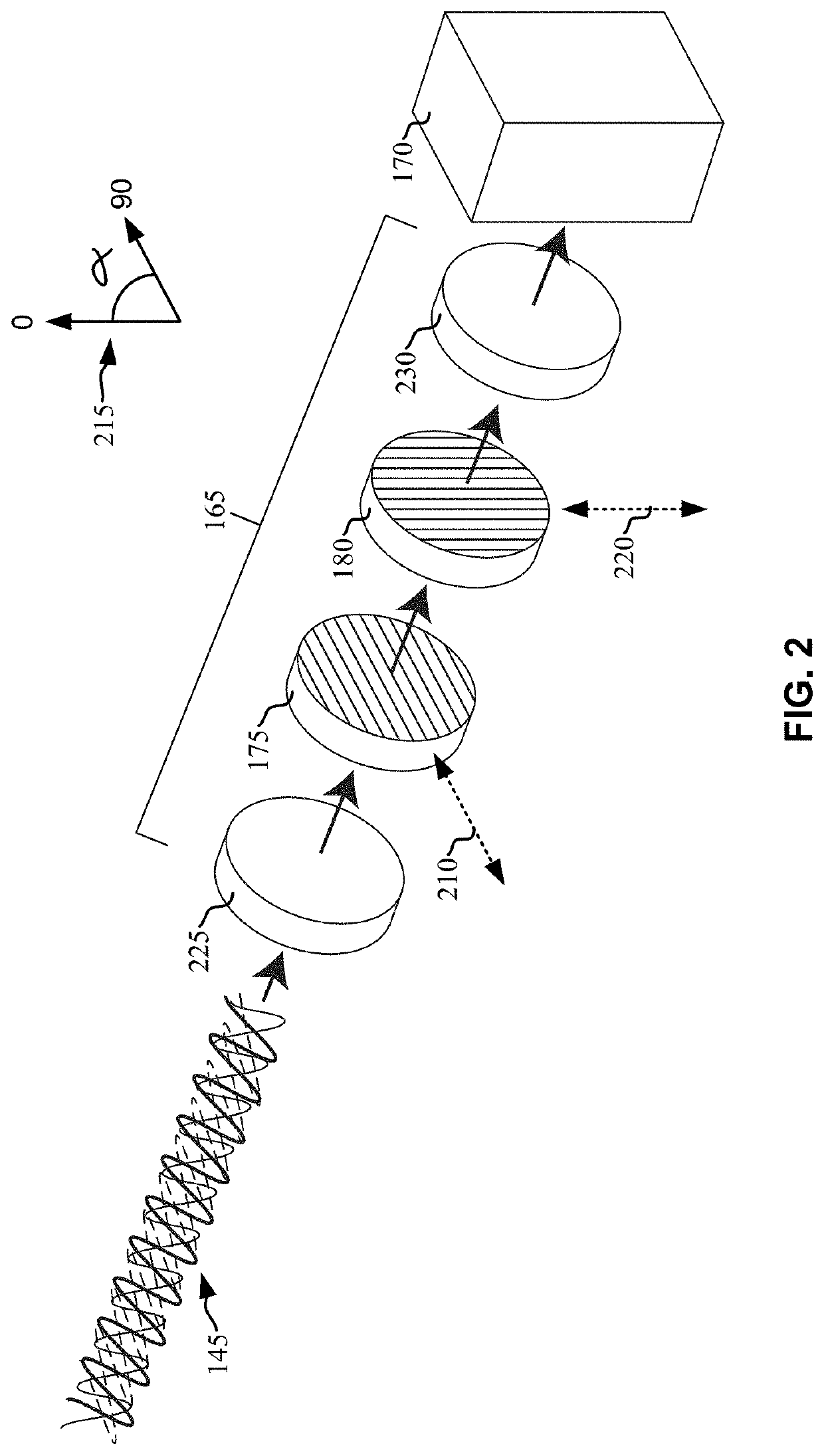
[0016]For example, in some embodiments an additive manufacturing system employs a laser energy source to melt and fuse a work region of metallic powder. An optical sensor receives light emitted from the melt pool and laser plume. The received light can be stochastic in nature and may include both spurious signals as well as mixed polarizations. The received light is passed through a first partially transmissive polarization filter having a first polarization axis and thr...


PUM

PropertyMeasurementUnit
transmittanceaaaaaaaaaa

Abstract

An additive manufacturing system comprises a build plane and an energy source configured to direct energy onto a work region of the build plane. An optical detector is configured to receive one or more optical signals from the work region. An optical filter is positioned between the work region and the optical detector, wherein the optical filter includes a first partially transmissive polarized filter having a first polarization axis and a second partially transmissive polarized filter having a second polarization axis. The first polarization axis is rotationally offset from the second polarization axis approximately 90 degrees. The optical filter improves the signal to noise ratio of the optical sensors.

Description

CROSS-REFERENCES TO OTHER APPLICATIONS[0001]This application claims priority to U.S. provisional patent application Ser. No. 62 / 933,154, for “REJECTION OF SPURIOUS LIGHT” filed on Nov. 8, 2019 which is hereby incorporated by reference in entirety for all purposes.BACKGROUND OF THE INVENTION[0002]Additive manufacturing, or the sequential assembly or construction of a part through the combination of material addition and applied energy, takes on many forms and currently exists in numerous implementations and embodiments. Additive manufacturing can be carried out by using any of a number of various processes that involve the formation of a three dimensional part of virtually any shape. The various processes have in common the sintering, curing or melting of liquid, powdered or granular raw material, layer by layer using ultraviolet light, high powered laser, or electron beam, respectively. During the manufacturing process optical noise is generated in the form of spurious light emissio...

Claims


Application Information

Patent Timeline
Patent Type & Authority Applications(United States)
IPC IPC(8): B23K26/03G02B5/30G02B27/28B33Y10/00B33Y30/00B33Y50/02B23K26/082
CPCB23K26/032G02B5/3025G02B27/281B23K26/342B33Y30/00B33Y50/02B23K26/082B33Y10/00Y02P10/25B22F12/90B22F10/28B22F10/85
Inventor BECKETT, DARRENPILTCH, MARTIN S.BETTS, SCOTTCASTRO, ALBERTO M.ANDERSON, KEVINJACQUEMETTON, LARSAGUILAR, LUIS
Owner SIGMA LAB OF ARIZONA
Why Eureka
Try Eureka