Eureka AIR delivers breakthrough ideas for toughest innovation challenges, trusted by R&D personnel around the world.

Mass spectrometer

a mass spectrometer and mass spectrometer technology, applied in mass spectrometers, instruments, particle separator tubes details, etc., can solve the problems of deterioration of some devices, disturbance of electric fields created, and gradual contamination of optical elements, so as to achieve high working efficiency, easy removal of fixation bands, and efficient performance

Active Publication Date: 2021-05-20
SHIMADZU CORP
View PDF0 Cites 4 Cited by
  • Summary
  • Abstract
  • Description
  • Claims
  • Application Information

AI Technical Summary

Benefits of technology

The present invention relates to a mass spectrometer with a vacuum chamber that has an ion beam axis extending in the front-to-rear direction. The side wall of the vacuum chamber is openable and closeable, allowing for easy removal and attachment of an ion optical element without needing to remove another device placed on top of the mass spectrometer. The attachment is performed through simple tasks, such as tightening or removing a screw, and the ion optical element can be accurately attached to a correct position. This results in a high level of working efficiency and prevents accidents. Overall, the technical effect of this invention is to simplify the removal and attachment process of an ion optical element without compromising the accuracy and safety of the mass spectrometer.

Problems solved by technology

Therefore, if the device is used for a long period of time, those ion optical elements gradually undergo contamination, and a disturbance occurs in the electric fields created by those elements.
Consequently, deterioration occurs in some performances of the device, such as the detection sensitivity or mass accuracy.
Accordingly, if the device performance has become unstable due to the contamination of an ion optical element (or the like), it is necessary to perform maintenance work which includes removing a quadrupole mass filter unit or collision cell from the device, cleaning the element(s) and other related tasks.
Therefore, LC-MS systems require comparatively large spaces for installation.

Method used


Image

  • Mass spectrometer
  • Mass spectrometer
  • Mass spectrometer

Examples


first embodiment

[0033]A mass spectrometer as the first embodiment of the present invention is hereinafter described with reference to the attached drawings.

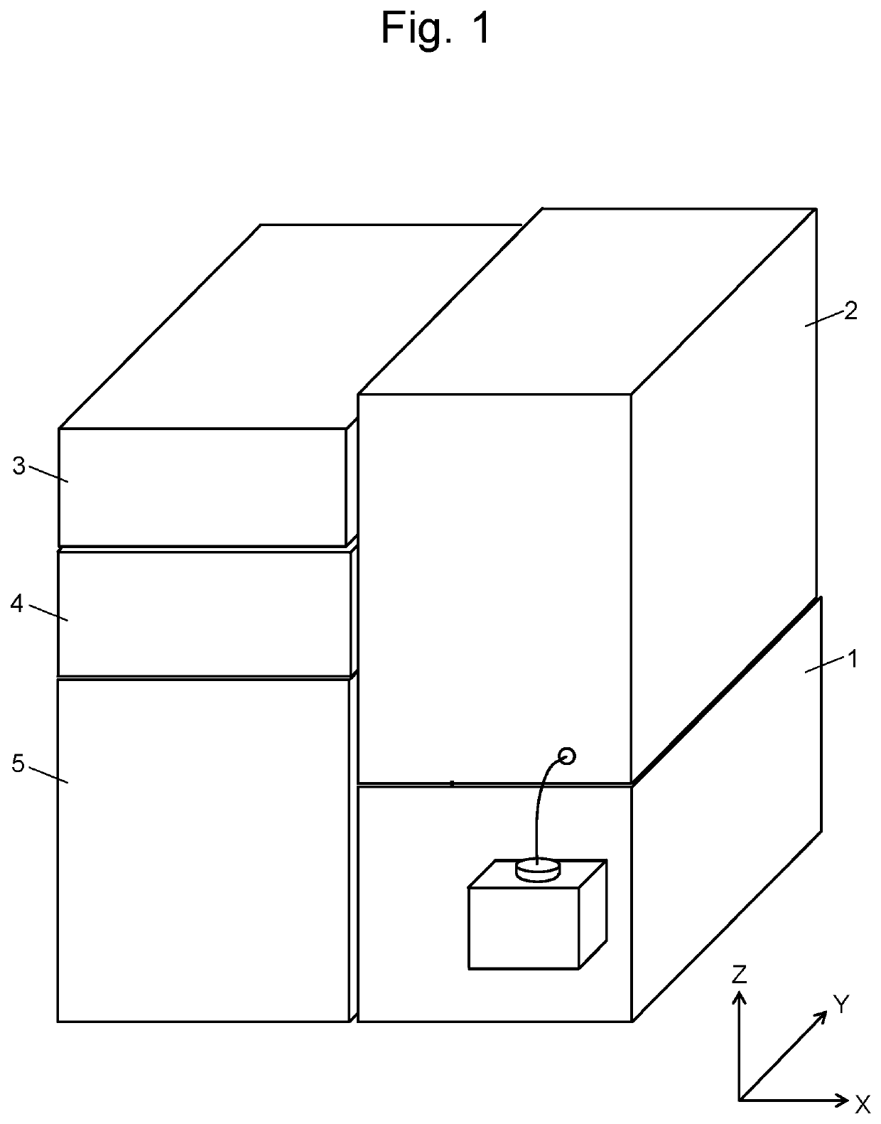
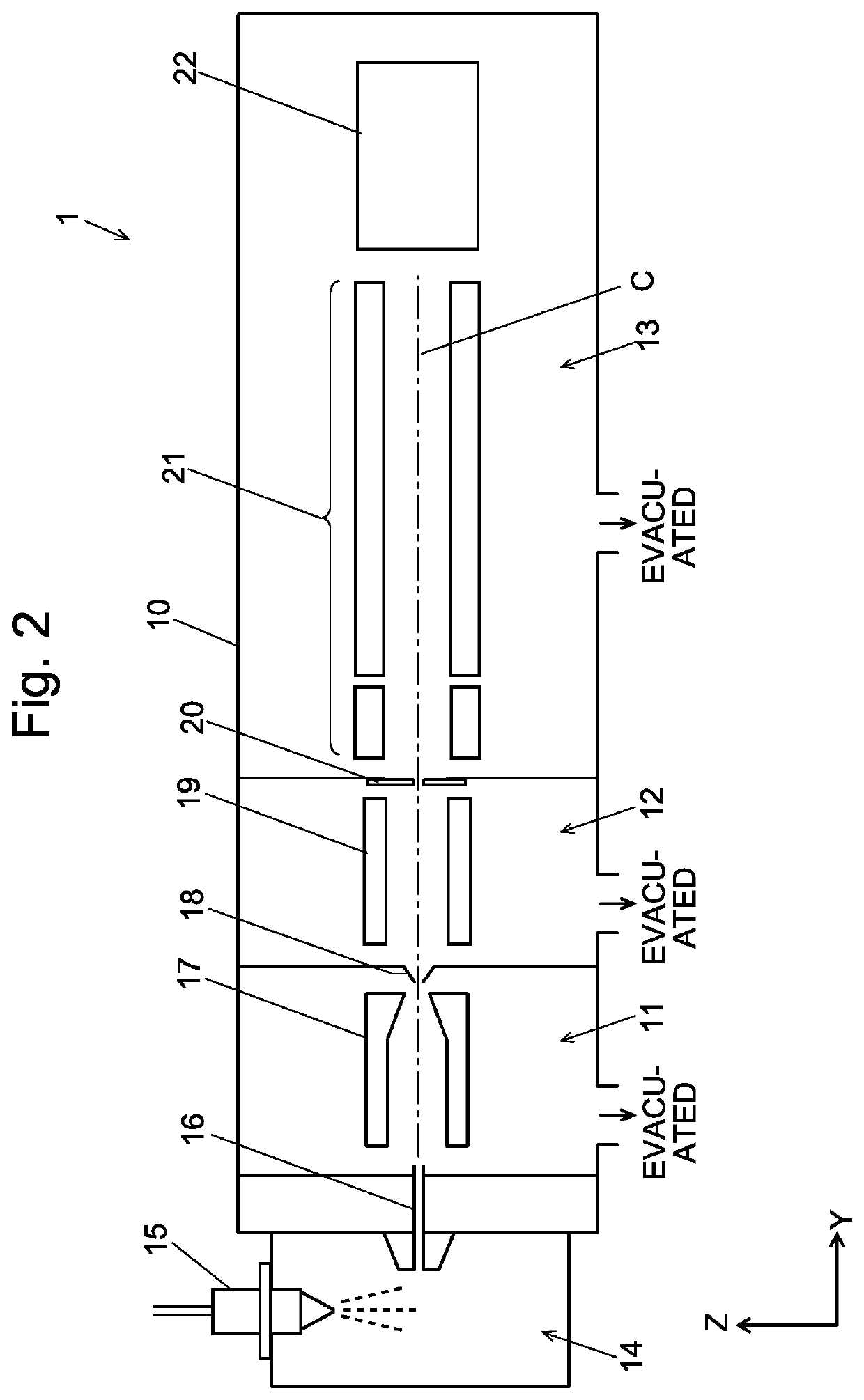
[0034]The present mass spectrometer is a single type of quadrupole mass spectrometer including an atmospheric pressure ion source employing an electrospray ionization (ESI) or similar method.

[0035]FIG. 1 is an external perspective view of an LC-MS system in which the mass spectrometer according to the first embodiment is used as the detector. This LC-MS system includes a mass spectrometer 1 as the detector unit, a column oven unit 2, two liquid supply units 3 and 4, as well as an injection unit 5. The liquid supply units 3 and 4 each include a mobile phase container holding a mobile phase, liquid supply pump, mixer and other components. The injection unit 5 includes an autosampler, injector and other components. The column oven unit 2 has a column inside. Those units each have a substantially rectangular-parallelepiped external shape and can be ...

second embodiment

[0058]A triple quadrupole mass spectrometer as the second embodiment of the present invention is hereinafter described with reference to FIGS. 6-8. FIG. 6 is a schematic vertical sectional view of a mass spectrometer according to the second embodiment as viewed from the front. FIG. 7 is a schematic plan view of the mass spectrometer according to the second embodiment with the right-side cover removed. FIG. 8 is a schematic plan view of the mass spectrometer according to the second embodiment with the right-side cover of the mass spectrometer and the side cover of the vacuum chamber removed. That is to say, FIGS. 6-8 corresponds to FIGS. 3-5 in the first embodiment. The components which are the same as or correspond to those of the mass spectrometer according to the first embodiment are denoted by the same reference signs.

[0059]As shown in FIG. 8, the high vacuum space 13 contains a front quadrupole mass filter 40 and a rear quadrupole mass filter 42 with a collision cell 41 sandwich...


PUM

PropertyMeasurementUnit
mass spectrometeraaaaaaaaaa
areaaaaaaaaaaa
outer diameteraaaaaaaaaa

Abstract

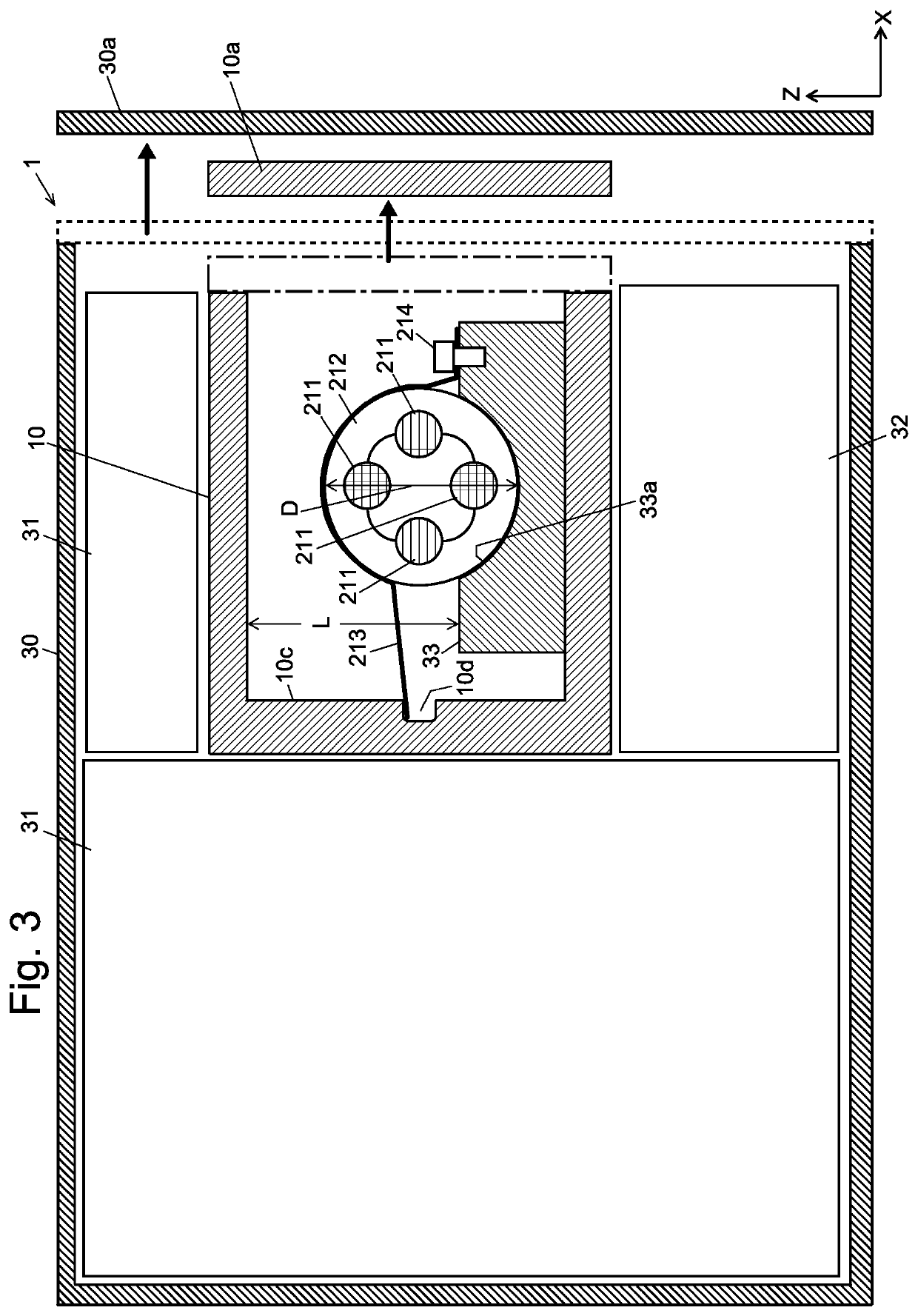
A vacuum chamber 11 for forming a vacuum space has two side walls opposite to each other across an ion beam axis extending within the vacuum space. One of those side walls is openable and closeable. An ion optical element 21 is placed on a base 33, which is located on the bottom surface of the vacuum chamber. A fixation band 213 fixes the ion optical element on the base by holding the element between the base and the fixation band so as to press the element onto the base. A band-catching portion 10d, located on an inside face of a side wall of the vacuum chamber on the opposite side from the openable-and-closeable side wall, catches one end of the fixation band. A band-fixing portion 214, located on the base on the side where the openable-and-closeable side wall is present, fixes the other end of the fixation band to the base.

Description

TECHNICAL FIELD[0001]The present invention relates to a mass spectrometer. The present invention is suitable for a mass spectrometer in which a quadrupole mass filter and / or collision cell is contained in an analysis chamber having a high degree of vacuum.BACKGROUND ART[0002]In a common type of quadrupole mass spectrometer, ions are generated from compounds in a sample within an ion source. The various generated ions are separated from each other according to their mass-to-charge ratios m / z by a quadrupole mass filter. The separated ions are detected with an ion detector. In the case of a triple quadrupole mass spectrometer including two quadrupole mass filters respectively located on the front and rear sides of a collision cell, the various ions generated in the ion source are separated from each other according to their mass-to-charge ratios by the front quadrupole mass filter so that an ion having a specific mass-to-charge ratio (precursor ion) is selectively introduced into the ...

Claims


Application Information

Patent Timeline
Patent Type & Authority Applications(United States)
IPC IPC(8): H01J49/42H01J49/24G01N30/72
CPCH01J49/4215G01N2030/027G01N30/72H01J49/24H01J49/0013H01J49/062H01J49/068H01J49/4225
Inventor UEDA, MANABUUMEMOTO, TAKASHI
Owner SHIMADZU CORP
Why Eureka
Eureka Blog
Learn More