
Depicting of objects

Pending Publication Date: 2021-05-27
CHEMOMETEC AS
View PDF12 Cites 2 Cited by
  • Summary
  • Abstract
  • Description
  • Claims
  • Application Information

AI Technical Summary

Benefits of technology

The present invention allows for the construction of image cytometers or microscopes that can perform well in all applications without the need for major optical components. Instead, small movements of optical components are used. Several methods of masking can be used for estimating the number of objects in a view, and the intensity of light information from an object can be reliably masked. This invention allows for the accurate and reliable analysis of image cytometry or microscopy samples.

Problems solved by technology

The previous methods of depicting objects, such as biological objects, based on the detection of fluorescence signal, have greatly suffered from complex protocols and obviously the limitation in the number of free fluorescent excitation / emission channels, thus resulting in tedious processes with unreliable performance due to fluorescence specificity.

Method used


Image

  • Depicting of objects
  • Depicting of objects
  • Depicting of objects

Examples


example 1

Imaging Conditions

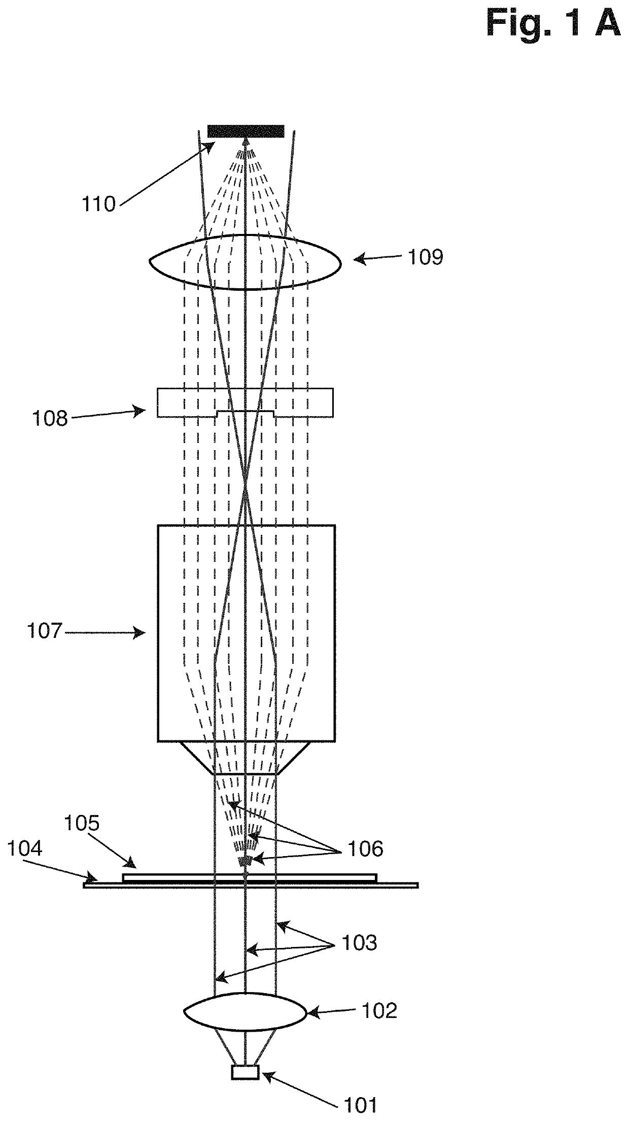
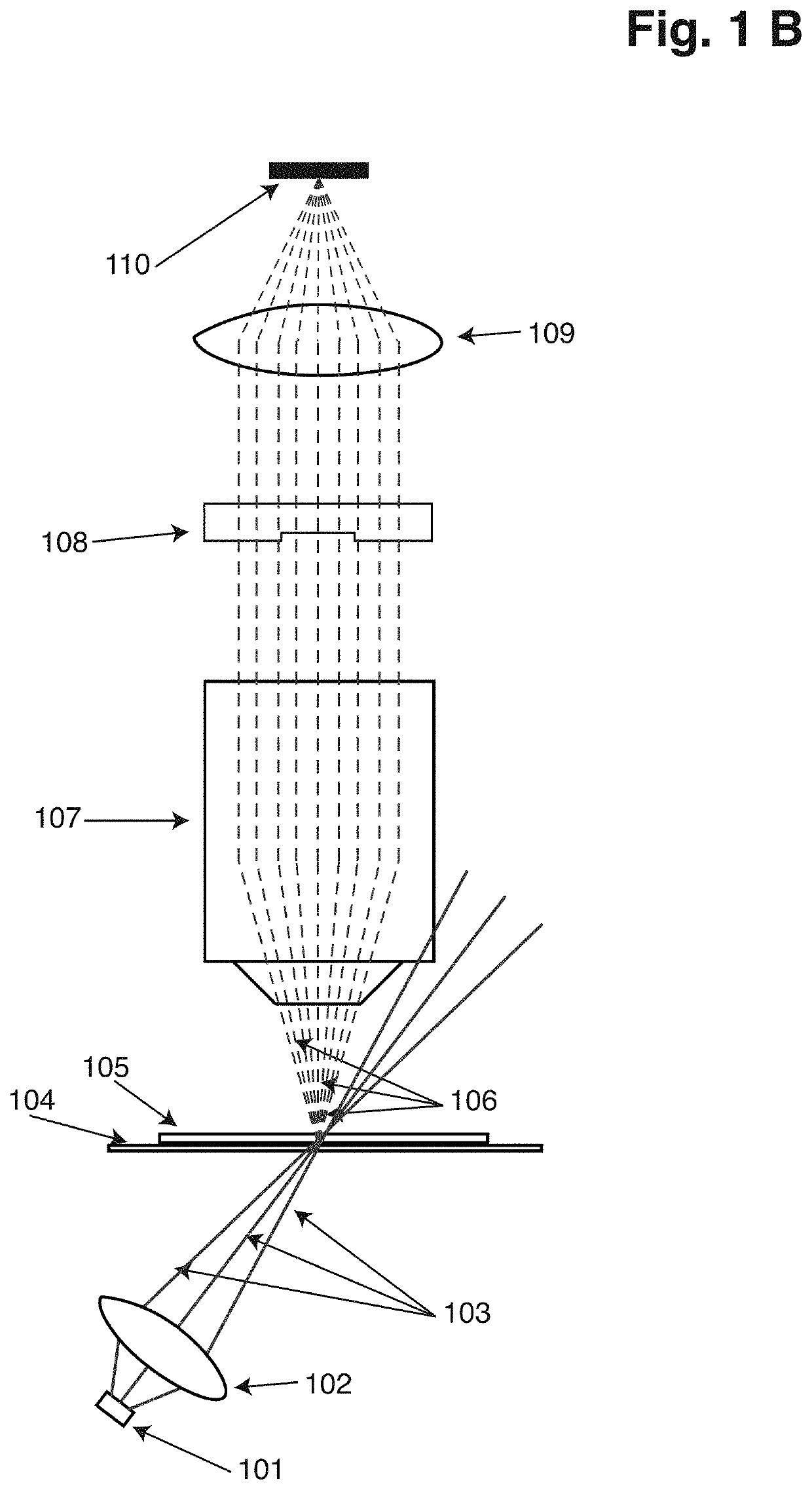
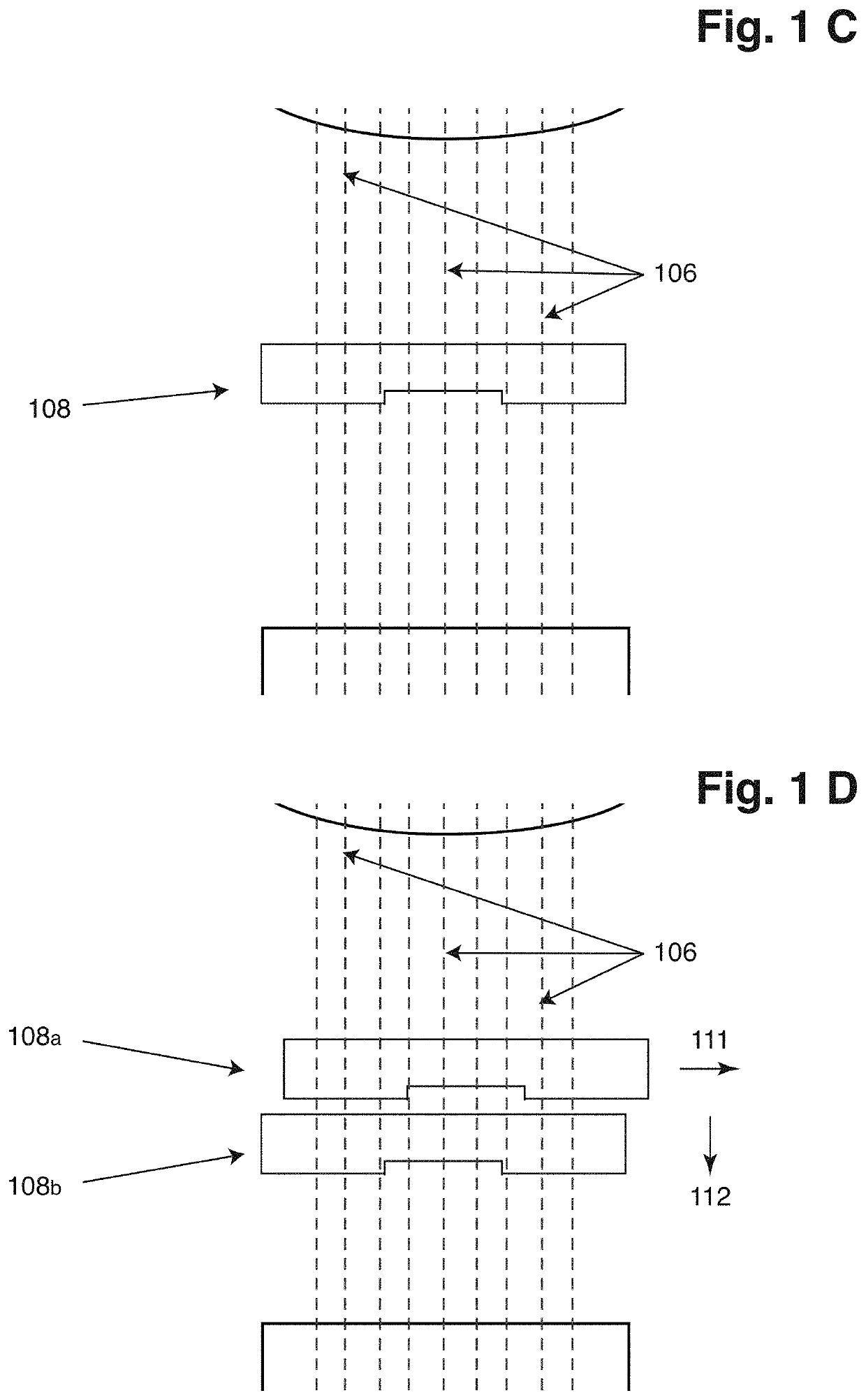
[0197]An Image Cytometer according to present invention, generally suitable for detection of phase-shift of light, is schematically illustrated in FIGS. 1A, 1B, 1C and 1D. The sample is illuminated by a light source (101) emitting light in a direction substantially parallel to the main optical axis in FIG. 1A. However, in FIG. 1B the sample is illuminated by a light source (101) emitting light at an inclination to the main optical axis. The illumination light is passed through optical means (102), such that it forms a beam of light (103) which either is substantially collimated or focused on the sample compartment, depending on the nature of the arrangement of the image cytometer.

[0198]A holder for the sample (104) supports the sample compartment (105) containing the sample being analyzed. When the beam of illumination light enters the sample, usually majority of it passes through the sample without any interaction with the sample or particles or objects in the sam...

example 2

Modulation Means

[0203]FIG. 2 presents schematic illustrations of modulation means, usually preferred in embodiments of the present invention. The nature of the modulation produced by the modulation means is usually preferred to be such as phase-shift or attenuation of light. The schematic illustration of FIGS. 2A, 2B and 2C present a cross-section of modulation means but do not disclose detailed mechanical design of the modulation means. Generally, modulation means of circular, square or rectangular shape are preferred in embodiments of the present invention.

[0204]FIG. 2A illustrates modulations means as a solid block (200), through which it is assumed that light traverses, the modulation means comprising along its diagonal line three different regions of modulation (201) presented as bars of different shade along one edge of the modulation mean.

[0205]Similarly FIG. 2B illustrates modulation means (210) comprising along its diagonal line five different regions of modulation (211). F...

example 3

Visualization

[0211]An image cytometer system according to the present invention was constructed, with a light source using Light Emitting Diode (LED) emitting light centred at about 365 nm in wavelength, arranged in alignment with the main optical axis of an image cytometer. The light illuminating the sample compartment was substantially collimated and homogenized, with respect to spatial intensity, using a lens system. The sample compartment comprised of two transparent glass wall parts, with U2OS cells growing on the bottom surface, forming a layer of adherent cells. The cell where fixed with formaldehyde and lysed with a solution containing Triton X-100. Prior to analysis the sample had been stained using a solution of DAPI, which since the cells had been lysed is expected to stain the nucleuses of the cells.

[0212]Light emitted from the sample was collected using a Nikon 4× objective (NA 0.2), forming a near parallel beam of light. The beam of light was focused, using a Nikon f-2...


PUM


Abstract

A method for characterizing object(s) in a sample includes collecting transmitted, refracted, scattered, diffracted, and / or emitted light from the sample. The collected light formed on a sensor surface includes at least a first and second image of the object(s). For at least the first and second image, the collected light is modulated asymmetrically differently, or for at least a third and fourth image focal plane positions are different, or for at least a fifth image the collected light is modulated in at least two places differently compared to the surroundings, or for at least a sixth and seventh image of the object(s), the collected light is modulated asymmetrically differently and focal planes of the sixth and seventh image have different positions. The images are processed to characterize the objects(s).

Description

CROSS-REFERENCE TO RELATED APPLICATIONS[0001]This application is the U.S. national stage of PCT / EP2019 / 059945 filed Apr. 17, 2019, which claims priority of European patent application 18167768.3 filed Apr. 17, 2018, both of which are hereby incorporated by reference in their entirety.FIELD OF THE INVENTION[0002]Current invention relates to the task of depicting or characterizing objects, such as biological particles and / or elements or parts of biological particles in image cytometry or in microscopy.DESCRIPTION OF THE RELATED ART[0003]Image Cytometry and microscopy are essential tools in the field of biology, as well as in other fields. The ability to visualize biological particles, both as individual particles or clusters of particles, but also the precise distribution of biomolecules within a single cell and the nucleus has provided scientist with vital information of cellular mechanisms for many decades. Main tools of Image Cytometry are general microscopy, where the direct inter...

Claims


Application Information

Patent Timeline
IPC IPC(8): G01N15/02G01N15/14G02B21/14
CPCG01N15/0227G01N15/1434G01N15/147G01N2015/1006G02B21/14G01N2015/0294G01N15/1475G02B21/241G02B21/16G01N2015/144G01N2015/1452G01N2015/1454G01N2015/1493G01N2015/1497G01N15/1433
Inventor HOLM, JOHAN
Owner CHEMOMETEC AS
Learn More