Lens System for a Video Endoscope, Endoscope Objective, Video Endoscope, and Assembly Method

a technology of endoscope and lens system, which is applied in the field of lens system for video endoscope, endoscope objective, video endoscope, and assembly method, can solve the problems of not being able to meet the requirements of endoscopes, the distal end section of the shaft of endoscopes is very limited, and the objective lens system employed for mobile phone cameras is not usually suitable for endoscopic applications. , to achieve the effect of facilitating assembly and stable and robust arrangemen

Pending Publication Date: 2021-05-27
KARL STORZ GMBH & CO KG
View PDF8 Cites 1 Cited by
  • Summary
  • Abstract
  • Description
  • Claims
  • Application Information

AI Technical Summary

Benefits of technology

[0037]Advantageously the spacers may be formed of glass or of a crystalline or metallic material. The spacers may be ring-shaped, being arranged approximately symmetrical to the optical axis. In this way a particularly stable and robust arrangement can be achieved, and assembly of the lens system is facilitated.
[0038]The endoscope objective may have an overall shape of a truncated cone or a truncated pyramid. In particular, the lens system may be enclosed in an approximately frustoconical or frustopyramidal casing, formed preferably of an opaque material such as, for example, a metallic material. The casing may be fixed to an object side of an electronic image sensor or a carrier or a package of an electronic image sensor, for example by an adhesive. Most preferably the base of the frustoconical or frustopyramidal casing has a cross dimension that does not exceed the corresponding dimension of the image sensor, including a substrate or packaging of the image sensor. The casing or a further spacer can be configured for adjusting the distance to the image sensor such that the sensor area is held in the image plane. In this way the endoscope objective as a whole can be easily and precisely mounted to the image sensor and inserted as a unit, including the image sensor, into the endoscope shaft, having its optical axis preferably aligned with a longitudinal axis of the shaft and the image sensor being perpendicular to the longitudinal axis.

Problems solved by technology

However, the available space in the distal end section of the shaft of an endoscope is very much limited.
On the other hand, several elements of the endoscope have considerable space requirements in the distal end section of the shaft, including, for example, illumination light guides and their related optics, and instrument channels, in addition to the endoscope objective.
Objective lens systems employed for cameras in mobile phones are not usually suitable for endoscopic applications.
Further, mobile phone objectives do not fulfill the requirements imposed on re-usable endoscopes regarding cleaning and sterilization.
Moreover, the optical image quality of mobile phones generally is inferior to that required in endoscopes.
Such micro-lens arrays may result in image deterioration, for example in color shifts in the edge areas of the image when used with standard COTT objectives.

Method used


Image

  • Lens System for a Video Endoscope, Endoscope Objective, Video Endoscope, and Assembly Method
  • Lens System for a Video Endoscope, Endoscope Objective, Video Endoscope, and Assembly Method
  • Lens System for a Video Endoscope, Endoscope Objective, Video Endoscope, and Assembly Method

Examples


Embodiment Construction

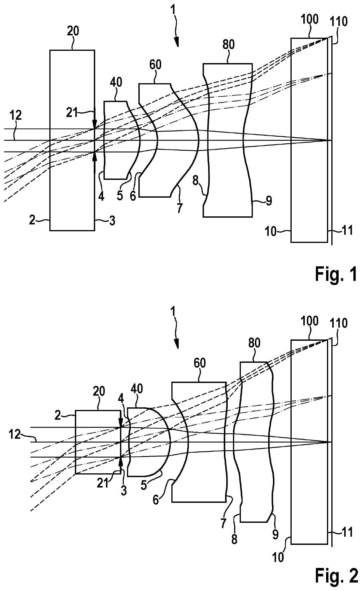
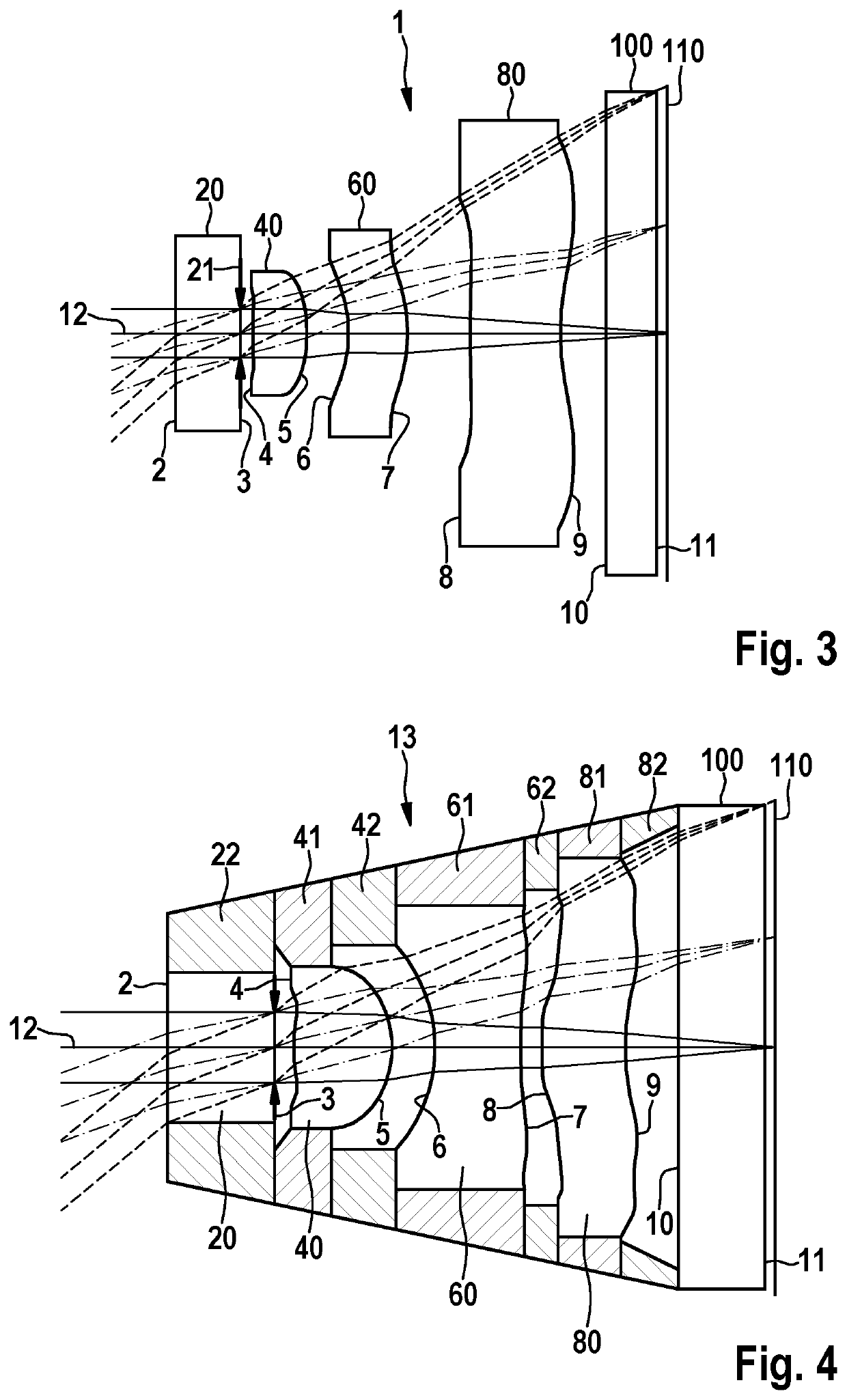
[0053]In FIGS. 1, 2, and 3 exemplary embodiments of a lens system in accordance with the present invention are shown in an axial sectional view. According to each of the embodiments shown the lens system 1 comprises optical surfaces 2-11, which are, in order from an object side, plane surfaces 2, 3 of a cover glass 20, aspheric surfaces 4, 5 of a first lens 40, aspheric surfaces 6, 7 of a second lens 60, aspheric surfaces 8, 9 of a third lens 80, and plane surfaces 10, 11 of a glass plate 100. Further to the image side an electronic image sensor 110 is arranged having its sensor plane in the focal plane of the lens system 1. The image sensor 110 may be a CCD, CMOS or a MOSFET sensor, for example.

[0054]Between the glass plate 100 and the image sensor 110 a micro-lens array is arranged (not shown). On the image-side surface 3 of the cover glass 20 an aperture stop 21 is formed, for example, by a ring-shaped diaphragm or by a coating on the surface 3 of the cover glass 20. FIGS. 1-3 al...


PUM


Abstract

A lens system (1) for a video endoscope comprises, in order from an object side, a cover glass (20), a first lens (40), a second lens (60) and one or more further lenses, wherein all lenses are single lenses. An aperture stop (21) is arranged at the object side of the first or the second lens (40, 60), all lenses on an image side of the aperture stop (21) are aspherical, all lenses are made of glass or of a crystalline material, and at least one lens has a refractive index n approximately equal to or exceeding 1.66. The invention also relates to an endoscope objective, to a video endoscope, and to a method for assembling an endoscope objective.

Description

CROSS REFERENCE TO RELATED APPLICATIONS[0001]This application claims priority to German Patent Application No. 102019008226.5, filed Nov. 26, 2019, and entitled, “Video endoscope and handle for a video endoscope,” and is incorporated herein by reference.FIELD OF THE INVENTION[0002]The present invention relates to a lens system for a video endoscope, to an endoscope objective comprising a corresponding lens system, to a video endoscope having such an objective, and to an assembly method for an endoscope objective.BACKGROUND OF THE INVENTION[0003]Endoscopes for medical or non-medical applications have an elongate shaft configured for being introduced into an internal cavity of a human or animal body or another object to be examined. The shaft may be rigid, semi-flexible, or flexible. Typically, the endoscope has a handle attached to a proximal (i.e. close to a user) end section of the shaft. In a distal (i.e. distant from a user) end section of the shaft an objective lens system is ar...

Claims


Application Information

Patent Timeline
Patent Type & Authority Applications(United States)
IPC IPC(8): G02B23/24G02B13/18A61B1/00A61B1/05
CPCG02B23/243A61B1/05A61B1/00197G02B13/18G02B23/2407G02B23/2484G02B13/0035G02B9/12
Inventor BAUMANN, HARALD
Owner KARL STORZ GMBH & CO KG
Why Eureka
Try Eureka