Photovoltaic modules and method of manufacture thereof

a technology of photovoltaic modules and photovoltaic cells, applied in the field of photovoltaic cells, can solve the problems of inability to directly use them, inability to apply extra layers to modules, and complex prior art solutions, so as to prevent migration and agglomeration, facilitate manufacturing, and high viscosity

Pending Publication Date: 2021-05-27
CSEM CENT SUISSE DELECTRONIQUE & DE MICROTECHNIQUE SA RECH & DEV
View PDF2 Cites 21 Cited by
  • Summary
  • Abstract
  • Description
  • Claims
  • Application Information

AI Technical Summary

Benefits of technology

[0040]The advantages of the present invention can thus be applied to pre-existing, prefabricated PV modules. The module of the invention can thus be fabricated to order based on existing, commercially-available modules. This is particularly efficient since coloured modules can then easily be fabricated to order based on a stock of standard, commercially-available modules.
[0041]Advantageously, said first film has a higher viscosity than said second film at all times during said application of heat and pressure, i.e. during lamination. As a result, the pigment particles distributed therein are more strongly prevented from migrating and agglomerating.
[0...

Problems solved by technology

When such PV devices are mounted on buildings, they can be unsightly, and it is often unacceptable to use them directly as building cladding for this reason.
However, this film requires a specific profile which necessitates alignment with the geometry of the individual PV cells making up the module, and relies on a complex design involving facets in the front sheet and embedded elements in the inactive part of the module.
However, all of these prior art solutions are either complex, or require extra layers to be applied to modules.
Essentially, for each additional layer added to a module, the risk of delamination of the module increases...

Method used


Image

  • Photovoltaic modules and method of manufacture thereof
  • Photovoltaic modules and method of manufacture thereof
  • Photovoltaic modules and method of manufacture thereof

Examples


Embodiment Construction

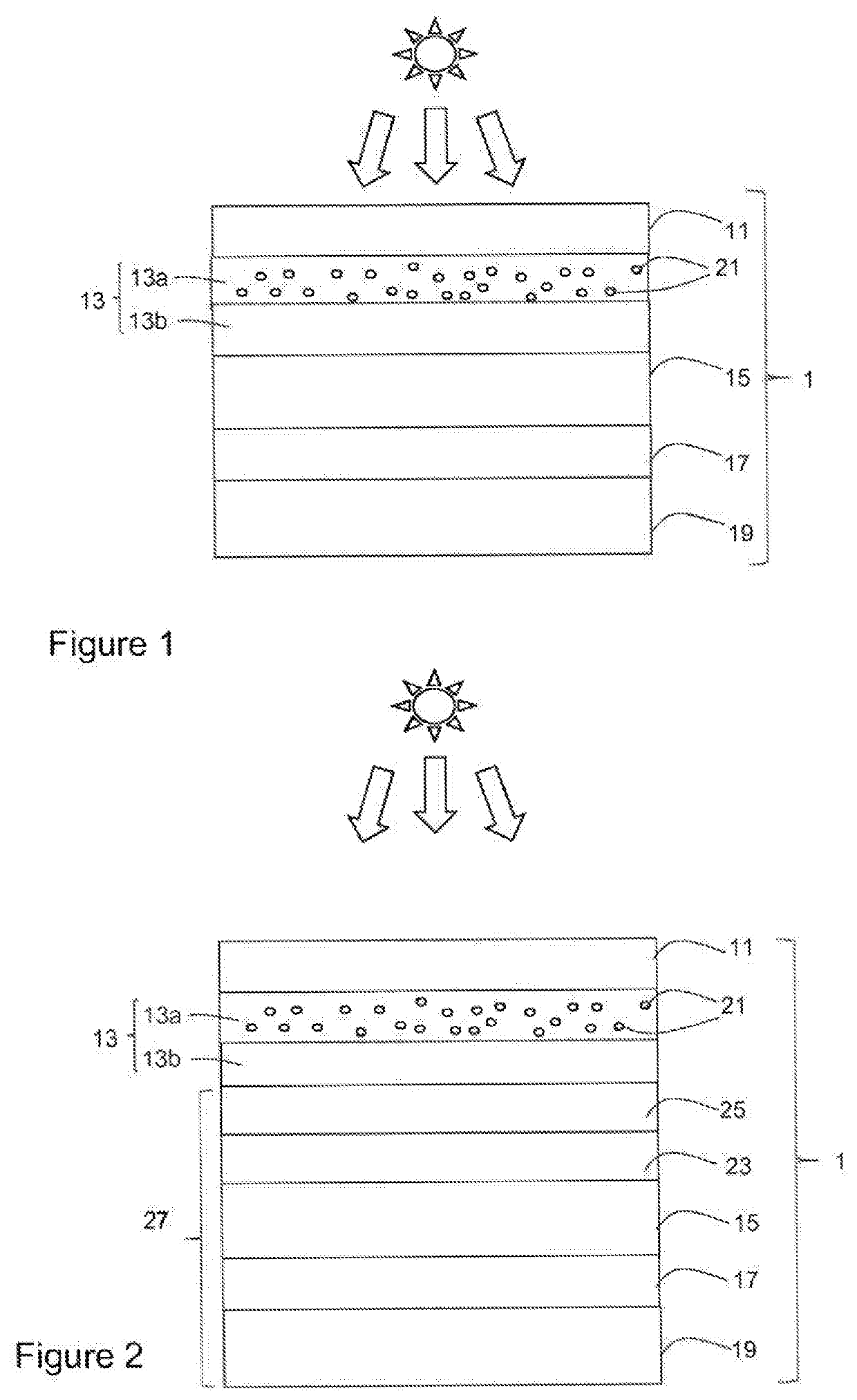
[0059]It should be noted in the following that, unless explicitly stated that a particular layer is disposed directly on the adjacent layer, it is possible that one or more intermediate layers can also be present between the layers mentioned. As a result, “on” should be construed by default as meaning “directly or indirectly on”. Furthermore, patterning of certain layers, connectors and so on are not represented since they are well-known to the skilled person.

[0060]FIG. 1 illustrates a first embodiment of a photovoltaic (PV) module 1 according to the invention.

[0061]This module 1 comprises a front sheet 11, on the light incident side of the module 1, intended to be illuminated when in use (as indicated in the figures by means of a sun symbol), and a back sheet 19, on the opposite side of the module 1 to the front sheet 11. The front sheet may be glass, transparent ceramic, polymer or any other convenient substantially transparent material, and the back sheet may be metal, glass, cer...


PUM


Abstract

Photovoltaic module comprising:
    • a front sheet arranged on a light incident side of said photovoltaic module;
    • a back sheet arranged on an opposite side of said photovoltaic module to said front sheet;
    • a photovoltaic conversion device disposed between said front sheet and said; back sheet;
    • at least one front encapsulation layer disposed between said photovoltaic conversion device and said front sheet and comprising pigment particles distributed therein;
characterized in that said, front encapsulation layer comprise a first zone a second zone, said first zone being situated closer said front sheet than said second zone, said first zone comprising a higher density of pigment particles than said second zone.

Description

TECHNICAL FIELD[0001]The present invention relates to the technical field of photovoltaic modules. More particularly, it relates to coloured photovoltaic modules particularly suited for building-integrated applications, as well as to methods of manufacture thereof.STATE OF THE ART[0002]The natural colour of photovoltaic (PV) devices, also referred to as solar cells or solar panels, tends to be near black, often with a purple or indigo tint, with a clearly-defined pattern of the individual cells being visible. When such PV devices are mounted on buildings, they can be unsightly, and it is often unacceptable to use them directly as building cladding for this reason.[0003]In order to overcome this issue, coloured PV devices have been proposed, which enable their integration into the structure of a building, notably as exterior cladding.[0004]Document U.S. Pat. No. 9,281,186 discloses a film placed on the front sheet of the PV device to modify the appearance of the module. However, this...

Claims


Application Information

Patent Timeline
IPC IPC(8): H01L31/048H01L31/049H01L31/054H01L31/18
CPCH01L31/0481H01L31/186H01L31/054H01L31/049H01L31/048Y02E10/52Y02B10/10H01L31/18
Inventor LI, HENGYUESCARRE PALOU, JORDISODERSTROM, KARINBULLIARD, XAVIERPERRET-AEBI, LAURE-EMMANUELLEBALLIF, CHRISTOPHE
Owner CSEM CENT SUISSE DELECTRONIQUE & DE MICROTECHNIQUE SA RECH & DEV
Why Eureka
Try Eureka