Artificial contractile structure

a contractile structure and artificial technology, applied in the field of artificial sphincters, can solve the problems of reducing the efficiency of the cuff so designed, requiring additional devices, and complicating surgery, so as to prevent the dissection of the vaginal wall, reduce the friction of the tensile elements, and facilitate folding.

Pending Publication Date: 2021-06-10
MYOPOWERS MEDICAL TECH FRANCE SAS
View PDF8 Cites 0 Cited by
  • Summary
  • Abstract
  • Description
  • Claims
  • Application Information

AI Technical Summary

Benefits of technology

[0020]In an embodiment, the artificial contractile structure may further comprise an arcuate self-supporting structure wherein said elongated member is installed, said self-supporting structure being configured for insertion on top of the circular striated muscle, thereby preventing dissection of the vaginal wall of a patient. Such configuration may be much favourable for implantation of female patients.
[0021]Advantageously, said closure may be integral with said elongated member, i.e. monobloc therewith, thereby resulting in a simple construction with a minimum number of pieces.
[0022]Advantageously, said tension system further comprises a flexible transmission attached pivotably to said elongated member, said first tensile element and said second tensile element passing through said flexible transmission. The flexible transmission can thus pivot with respect to the elongated member without kinking, which is useful not only in use, but also when being inserted into the patient by means of a trocar, since it can be easily folded up alongside the cuff. The cuff and the flexible transmission together constitute a medical device.
[0023]Advantageously, said flexible transmission is attached to an adaptor, said adaptor comprising at least one pulley around which said first tensile element and said second tensile element pass so as to enter into said flexible transmission. The one or more pulleys may be rotary or fixed, and serve to minimise friction with the tensile elements when they make the transition from the cuff into the flexible transmission.
[0024]Advantageously, a control system comprising an actuator is provided, said first tensile element and said second tensile element being attached to said actuator by means of an connector, said connector being attached to said actuator by means of a push-fit connection. Connection of the tensile elements and the flexible transmission to the actuator is thus simple, and does not require any rotation.

Problems solved by technology

In acute testing, this artificial contractile structure has shown promise in treating male incontinence, however it has certain drawbacks in treating the same condition in females, since its shape is insufficiently adapted to the female urethra.
When applying strength on the cable, the portion extending beyond the locking system present a lower resistance to contraction and would contract first, decreasing the efficiency of the cuff so designed.
Whereas ways to strengthen this portion -so-called “dead zone” so that the contractile portion surrounding the urethra contracts in priority exist, they require additional devices and complicate the surgery.
Due to the female urethras being bigger than male urethras and their anatomical condition very different, the pulling distance needed to contract the structure may exceed the actual length of the structure disclosed in WO2015 / 117664 and, as such, may not achieve the intended pull distance required to make the patient continent again on the long term.
However, in long-term use, slings often fail as constant pressure of the slings on soft tissues leads to erosion or migration of slings through the urethra., thereby reducing the pressure applied to the urethra, and require placement of yet another sling.

Method used


Image

  • Artificial contractile structure
  • Artificial contractile structure
  • Artificial contractile structure

Examples


Embodiment Construction

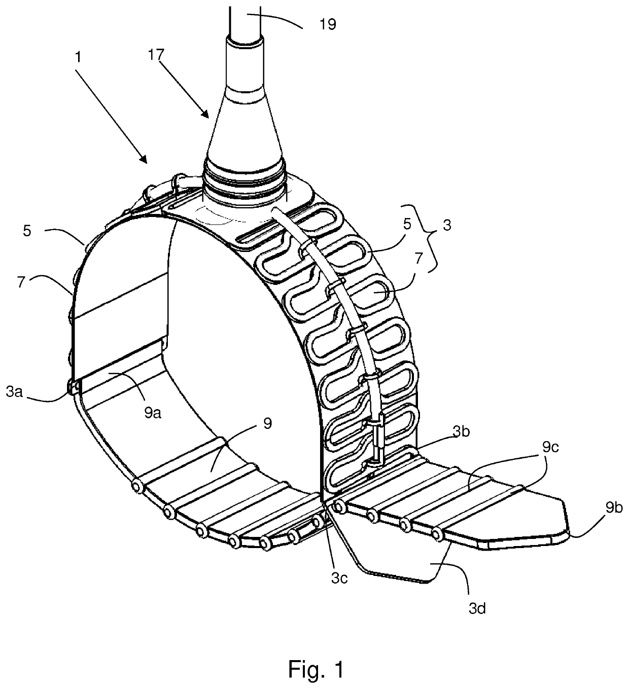
[0050]FIG. 1 illustrates an artificial contractile structure 1 according to the invention. Such artificial contractile structures are often referred to as “cuffs”, and this term will be used interchangeably with “artificial contractile structure” in the following description for ease of readability.

[0051]The cuff 1 comprises an elongated member 3, i.e. a long, relatively thin member which may be a strip of substantially flat cross-section or may have a V-shaped, U-shaped or corrugated cross-section (or similar), comprising a resilient core 5 and a biocompatible outer sheath 7. The elongated member 3 would typically be considered as being substantially flat, even if it comprises longitudinal corrugations or other similar structures; in other words, “flat” is not to be construed as being synonymous with “planar”.

[0052]In the illustrated embodiment, the resilient core 5 is formed as a lattice of a resilient, elastic material such as a metal, however certain polymers such as SMPs (Shape...


PUM


Abstract

Artificial contractile structure (1) for a medical device, said artificial contractile structure (3) comprising:—an elongated member (3) adapted to contact a hollow body organ;—a closure (9) adapted to form the artificial contractile structure (1) into a closed loop around said hollow body organ;—a tension system (11) arranged to be connected to a control unit (28), said tension system (1) being adapted to modify an internal diameter of said closed loop in response to a force applied by said control unit (28). According to the invention, said elongated member (3) comprises a resilient core (5) and a biocompatible outer sheath (7). Said tension system (11) furthermore comprises a first tensile element (13) attached to a first point (3c) of said elongated member, and a second tensile element (15) attached to a second point (3d) of said elongated member, each of said tensile elements (15, 17) passing through an adaptor (17) situated between said first point (3c) and said second point (3d).

Description

TECHNICAL FIELD[0001]The present invention relates to the field of artificial sphincters, in particular, but not exclusively, for the treatment of urinary incontinence.BACKGROUND ART[0002]WO2015 / 117664 describes a form of mechanical artificial contractile structure proposed as an alternative to problematic hydraulic systems such as the AUS 800 marketed by American Medical Systems, Inc. The artificial contractile structure disclosed in the above-mentioned document comprises a flat strip arranged to be closed in a loop around the urethra (or any other hollow body organ) of a patient by means of a closure. Once applied to the hollow body organ, this latter can be constricted by means of tension applied by a wire passing through the structure of the strip. A series of lateral reinforcing elements are formed on outer side of the strip, which cause it to adopt a substantially U-shaped cross-section when said tension is applied, and thus to gently apply pressure to the organ.[0003]In acute...

Claims


Application Information

Patent Timeline
Patent Type & Authority Applications(United States)
IPC IPC(8): A61F2/00
CPCA61F2/005A61F2210/0014A61F2250/001A61F2/0036
Inventor AUBERT, CHRISTOPHEKAEGI, FABIANCABAUD, FRANCOIS
Owner MYOPOWERS MEDICAL TECH FRANCE SAS
Why Eureka
Try Eureka