
Self-assembled monolayers as sacrificial capping layers

a self-assembled monolayer and capping layer technology, applied in the direction of basic electric elements, semiconductor/solid-state device manufacturing, electric apparatus, etc., can solve the problems of dielectric failure, affecting the reliability of cu metal interconnects, dielectric capping layers, dielectric etching, etc., to prevent metal diffusion and prevent oxidation and contamination of metal surfaces

Pending Publication Date: 2021-06-10
TOKYO ELECTRON LTD
View PDF2 Cites 2 Cited by
  • Summary
  • Abstract
  • Description
  • Claims
  • Application Information

AI Technical Summary

Benefits of technology

The patent describes a way to protect metal surfaces from being invaded by other materials and becoming contaminated during processing. This is accomplished by depositing a layer of material that acts as a temporary "cap" to prevent these things from happening. The method then allows for the temporary protective layer to be removed, providing a clean metal surface for further processing.

Problems solved by technology

Many metals diffuse easily into dielectric materials under thermal and / or electric stress, thereby causing a dielectric failure.
Ta / TaN or CoWP capping layers have been used but the process of selectively depositing a metal capping layer on the Cu metal and subsequently removing the metal capping layer is problematic and can affect reliability of the Cu metal interconnects.
Furthermore, dielectric capping layers and dielectric etch stop layers (e.g., SiN, SiC, SiCN, and SiCO) have been used but are difficult to deposit selectively on Cu metal surfaces.

Method used


Image

  • Self-assembled monolayers as sacrificial capping layers
  • Self-assembled monolayers as sacrificial capping layers
  • Self-assembled monolayers as sacrificial capping layers

Examples


Embodiment Construction

[0011]A substrate processing method is described. The substrate may include any material group or structure of a device, particularly a semiconductor or other electronics device, and may, for example, be a base substrate structure, such as a semiconductor substrate or a layer on or overlying a base substrate structure such as a thin film. Thus, the substrate is not intended to be limited to any particular base structure, underlying layer or overlying layer, patterned or unpatterned, but rather, is contemplated to include any such layer or base structure, and any combination of layers and / or base structures. The description below may reference particular types of substrates, but this is for illustrative purposes only and not limitation. The substrate may include a round substrate (wafer) with a diameter of at least 150 mm, 200 mm, 300 mm, or 450 mm.

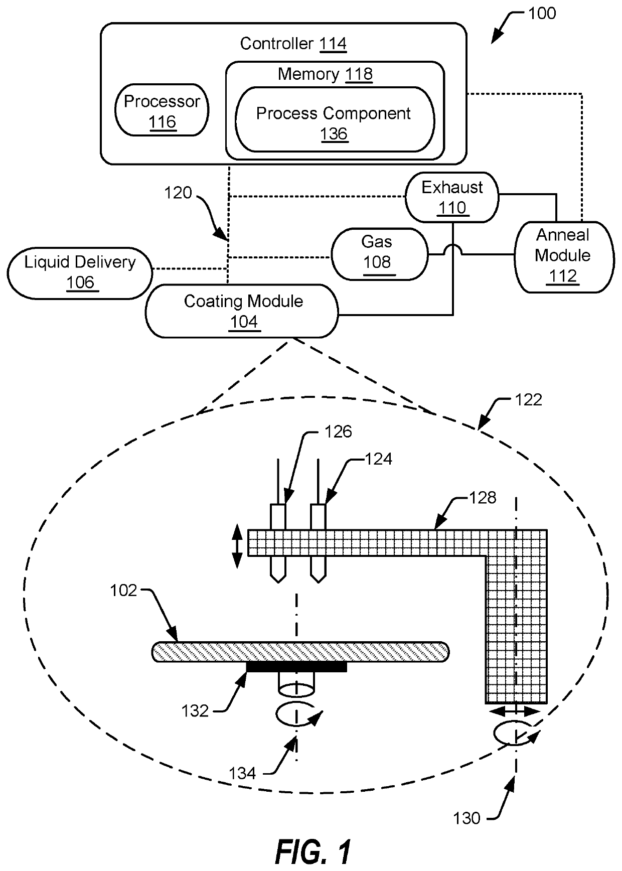
[0012]FIG. 1 depicts a spin-coating processing system 100 for dispensing chemicals onto a substrate 102 using a coating module 104 that i...


PUM

PropertyMeasurementUnit
temperatureaaaaaaaaaa
diameteraaaaaaaaaa
diameteraaaaaaaaaa

Abstract

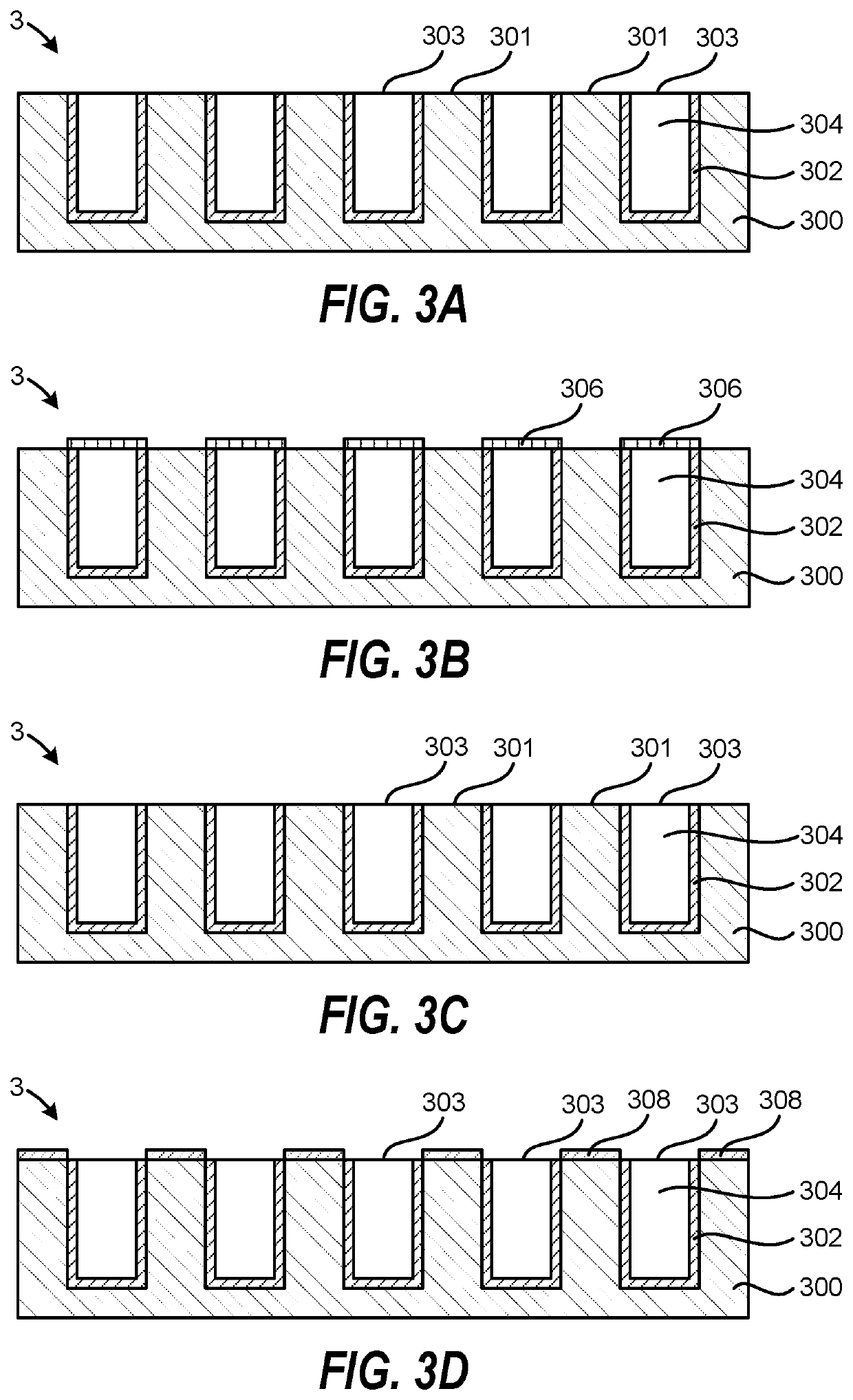
A substrate processing method includes providing a substrate containing a metal surface and a dielectric material surface, selectively forming a sacrificial capping layer containing a self-assembled monolayer on the metal surface, removing the sacrificial capping layer to restore the metal surface, and processing the restored metal surface and the dielectric material surface. The sacrificial capping layer may be used to prevent metal diffusion into the dielectric material and to prevent oxidation and contamination of the metal surface while waiting for further processing of the substrate.

Description

CROSS-REFERENCE TO RELATED APPLICATIONS[0001]This application claims priority to U.S. Provisional Patent Application No. 62 / 946,243, entitled, “Self-Assembled Monolayers as Sacrificial Capping Layers,” filed Dec. 10, 2019; the disclosure of which is expressly incorporated herein, in its entirety, by reference.FIELD OF THE INVENTION[0002]The present invention relates to semiconductor processing and semiconductor processing systems, and more particularly, to a method for forming self-assembled monolayers as sacrificial capping layers to protect exposed materials during semiconductor processing.BACKGROUND OF THE INVENTION[0003]Many metals diffuse easily into dielectric materials under thermal and / or electric stress, thereby causing a dielectric failure. In semiconductor devices, copper (Cu) metal is used as an interconnecting conductor in order to provide low electrical resistance within the devices. In order to prevent metal diffusion, Cu metal deposited in recessed features is surrou...

Claims


Application Information

Patent Timeline
Patent Type & Authority Applications(United States)
IPC IPC(8): H01L21/768H01L21/02H01L21/687
CPCH01L21/76834H01L21/02164H01L21/68764H01L21/02301H01L21/02318H01L21/02282H01L21/32H01L21/6715H01L21/76883H01L21/76829
Inventor NEGREIRA, AINHOA ROMOKAWANA, YUMIKOTRIYOSO, DINA
Owner TOKYO ELECTRON LTD
Learn More