
Manufacturing method for semiconductor device

a manufacturing method and semiconductor technology, applied in semiconductor/solid-state device manufacturing, basic electric elements, electric devices, etc., can solve the problems of deterioration of transistor properties and properties, deterioration of quality and properties of manufactured semiconductor devices, and significant deterioration of semiconductor devices. , to achieve the effect of preventing metal diffusion, increasing the number of steps, and preventing metal diffusion into the semiconductor substra

Inactive Publication Date: 2009-03-05
SHARP KK
View PDF5 Cites 0 Cited by
  • Summary
  • Abstract
  • Description
  • Claims
  • Application Information

AI Technical Summary

Benefits of technology

[0025]In view of the above-described problems, an object of the present invention is to provide a simple manufacturing method for a semiconductor device in which increase in the number of steps is restricted to the minimum and which can prevent metals from diffusing into a semiconductor substrate.
[0029]Here, as described above, the first to third material films are formed in regions other than on the main surface side after carrying out the fifth step. From among these films, the third material film is on the outermost side, and the second material film and the first material film are formed in this order toward the inside, that is, toward the semiconductor substrate side. On the other hand, a buried insulating film is formed in the trench structure portion on the main surface side, and the second material film and the first material film are formed in portions other than the trench structure in this order from the outside inward (semiconductor substrate side). When the second material film on the main surface side is etched and removed by carrying out a wet etching process using the second etchant in this state, the third material film, of which the etching rate for the second etchant is lower than that of the second material film, is formed on the outermost side in regions other than the main surface side, and therefore, the etching process in the sixth step can be carried out without having to worry about the decrease of the thickness of the second material film formed inside the third material film.
[0030]As a result, even after the completion of the sixth step, a state where the third material film remains in regions other than the main surface side is maintained. When the first material film on the main surfaces side is etched and removed in this state by carrying out a wet etching process using the first etchant in the seventh step, the third material film, of which the etching rate for the first etchant is lower than that of the first material film, still remains on the outermost side in regions other than the main surface side, and therefore, the etching process in the seventh step can be carried out without having to worry about the decrease of the thickness of the first material film formed inside the third material film.
[0031]That is, in the manufacturing method for a semiconductor device according to the above-described first aspect of the present invention, it is not necessary to add a separate photolithographic step and the like in order to form only a material film for preventing metal diffusion, and thus, a material film for preventing metal diffusion can be formed on the sides and rear surface side of a semiconductor substrate through the same steps as those used to form conventional STI structures.
[0037]In the configuration of the present invention, a semiconductor device having effects of preventing metal diffusion into the semiconductor substrate can be manufactured in accordance with a simple manufacturing method while an increase in the number of steps is limited to the minimum. Accordingly, metal diffusion into the semiconductor substrate can be easily prevented, even in the case where a metal material having a high diffusion coefficient, such as Cu, is used as the material for the wires.

Problems solved by technology

In the manufacture of conventional semiconductor devices, the quality and properties of the manufactured semiconductor devices significantly deteriorate when an impurity of a metal, particularly a heavy metal, is mixed in the inside of the semiconductor substrate.
In solid state imaging devices, for example, the presence of heavy metal contaminants in the semiconductor substrate causes and / or induces defects, and thus is a factor in the deterioration of the transistor properties and properties in the dark of the solid state imaging device.
However, since Cu has a high diffusion coefficient, there is a fear that Cu may diffuse into the semiconductor substrate and cause the properties to deteriorate, as described above.
In the case of the method described in Publicly Known Document 1, however, a photolithographic step, in which the polysilicon film 104, the silicon nitride film 105 and the photoresist 106 are applied, and a subsequent step for oxidizing the polysilicon film 104 are necessary in order to coat the peripheral portion on the main surface and on the outer peripheral surface and the rear surface of the semiconductor substrate, with the silicon nitride film 103 and the silicon oxide film 107, and thus a problem arises in which a great number of steps are required in addition to those in usual methods for forming an STI structure.
The steps for forming these films 104 and 105 are not required when the STI structure is formed, but are required only when a protective insulating film is formed, and therefore, may become a factor in the high cost of manufacture.
Therefore, there is a problem that it is required to control the film thickness to a considerably high degree in order to keep good balance in the film thickness of the silicon nitride film 203 between the main surface side and the rear surface side of the semiconductor substrate 201.
Accordingly, it becomes difficult to control etching so that a film thickness required in order to gain the effects of preventing metal contaminants from diffusing into the semiconductor substrate remains.

Method used


Image

  • Manufacturing method for semiconductor device
  • Manufacturing method for semiconductor device
  • Manufacturing method for semiconductor device

Examples


Embodiment Construction

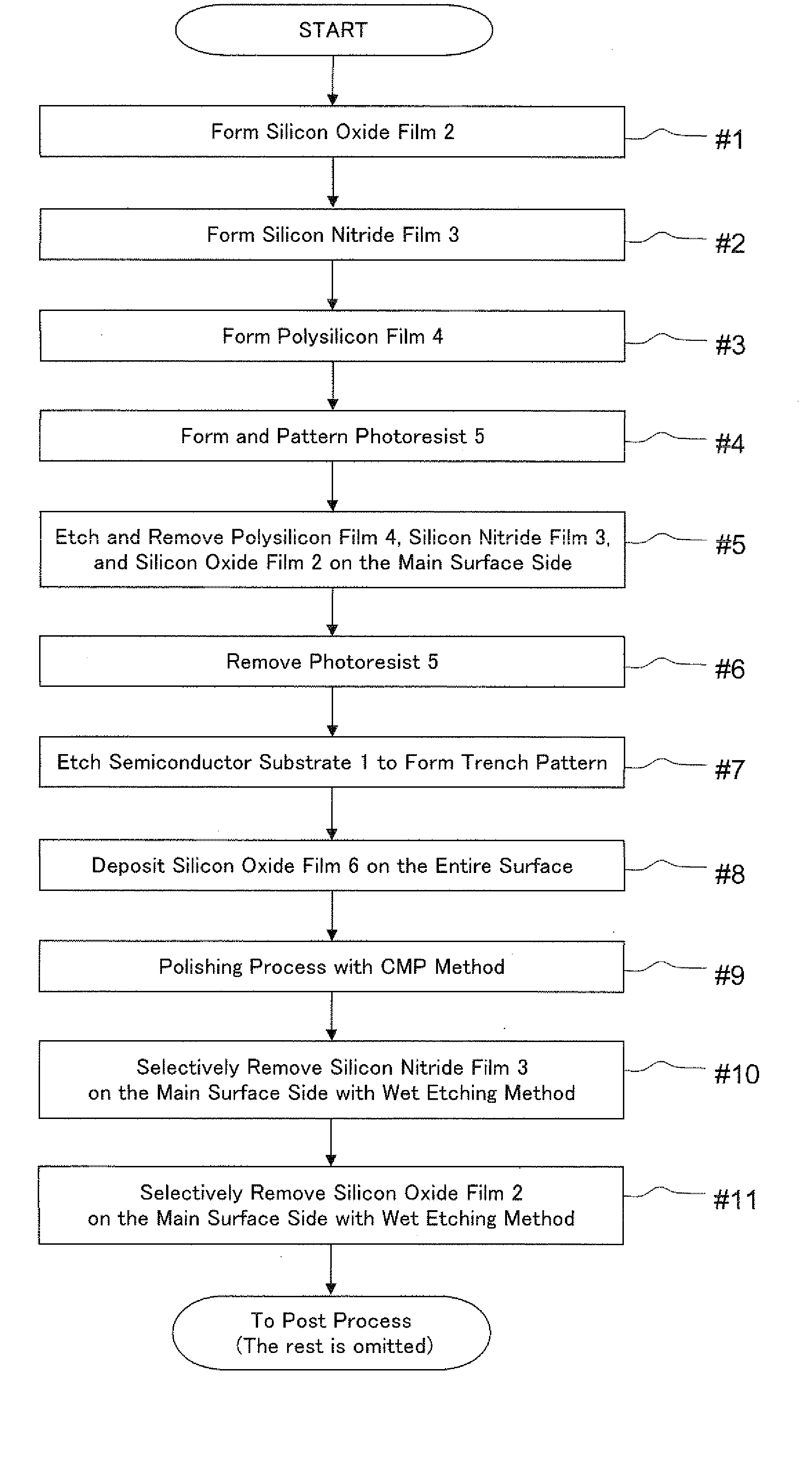
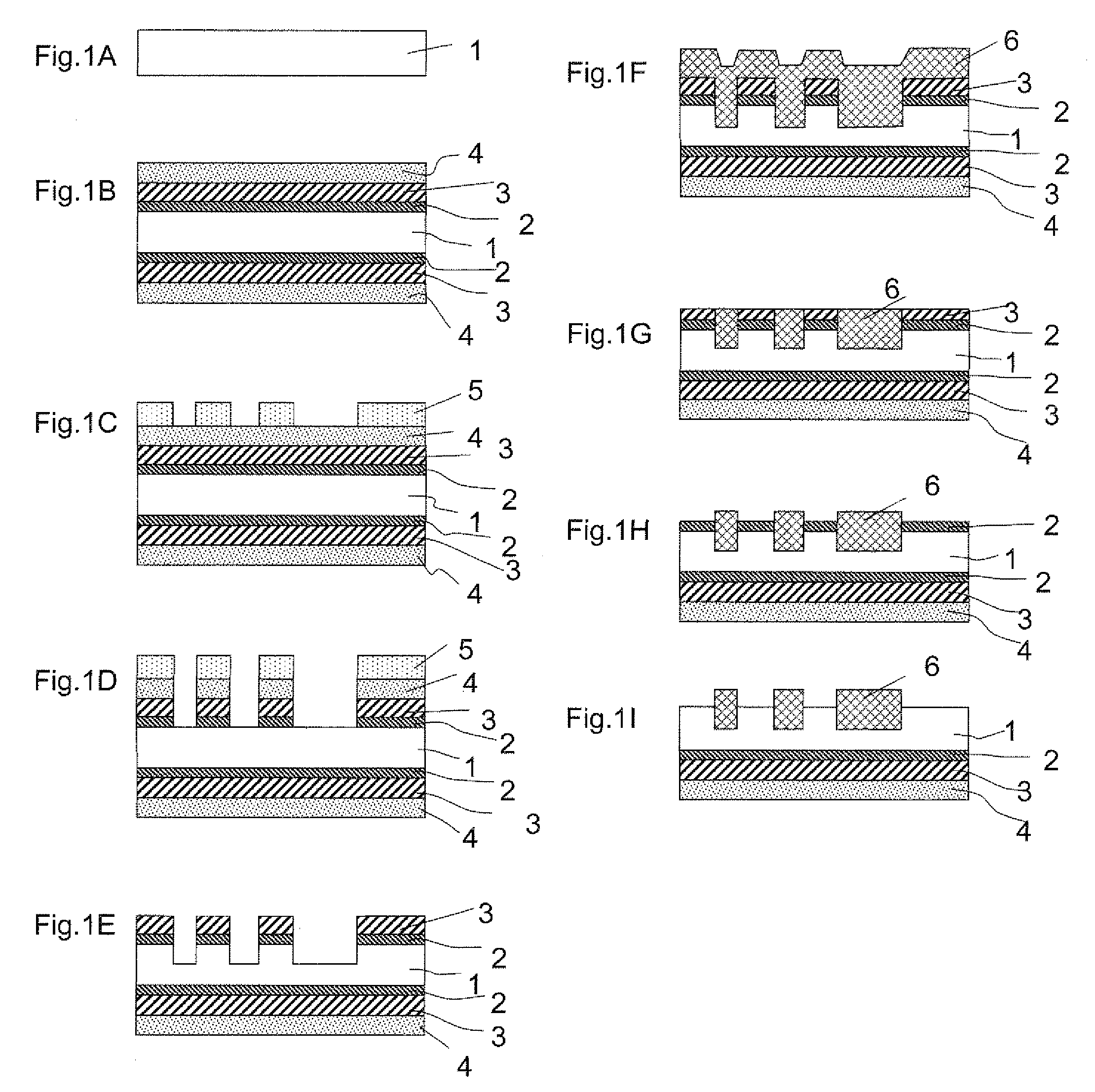
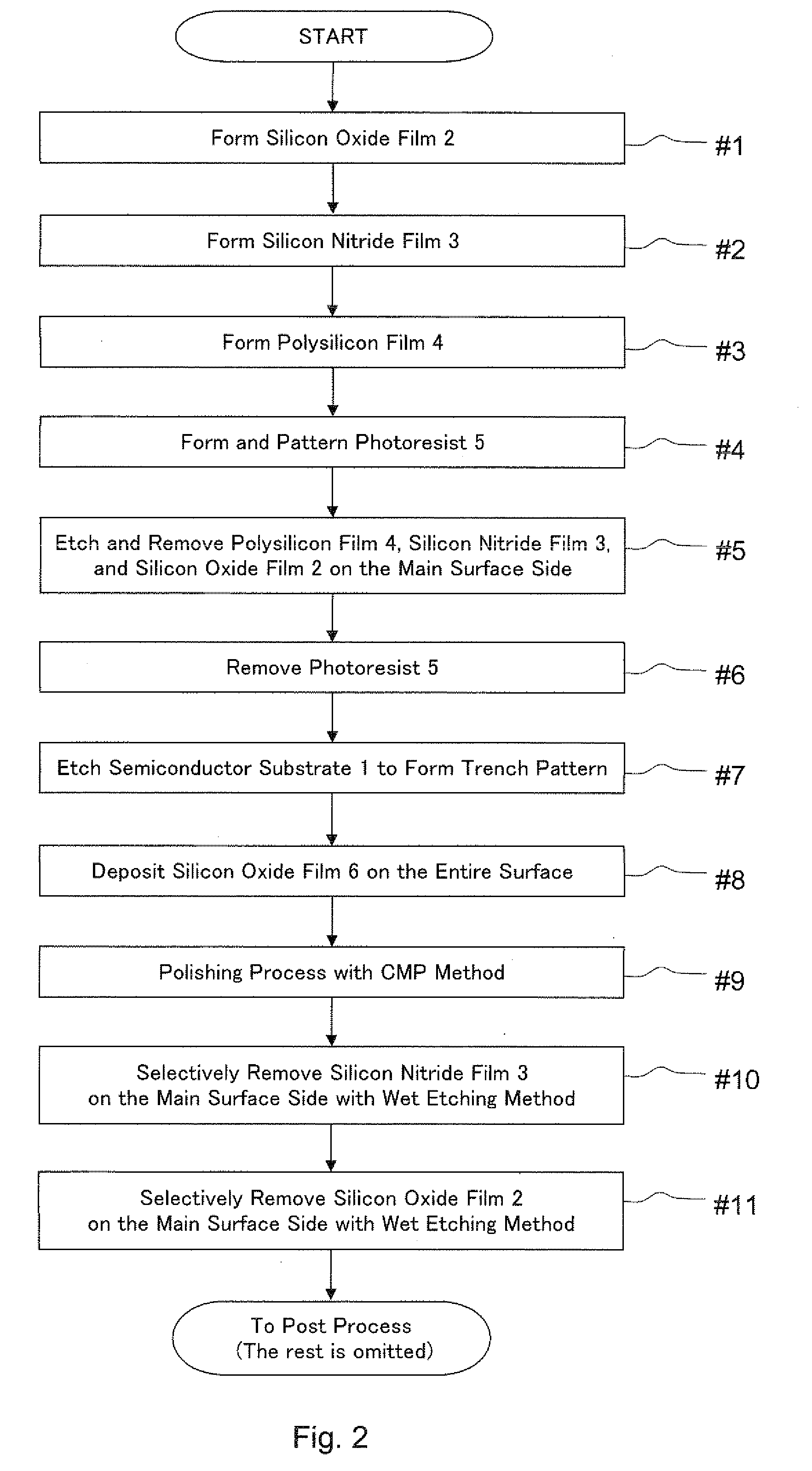
[0042]In the following, the manufacturing method for a semiconductor device according to an embodiment of the present invention (hereinafter referred to as “method according to the present invention”) is described in reference to FIGS. 1 and 2.

[0043]FIGS. 1A to 1I are schematic cross sectional views illustrating the structure in each step when a semiconductor device is manufactured using the method according to the present invention. Each of FIG. 1A to 1I shows each steps. In addition, FIG. 2 is a flow chart illustrating the manufacturing steps using the method according to the present invention, and each step in the following description represents one step in the flow chart shown in FIG. 2.

[0044]Here, FIGS. 1A to 1I are schematic cross sectional views showing the structure, and the scale in the drawings does not necessarily correspond to the actual scale.

[0045]First, as shown in FIG. 1A, a silicon oxide film 2 is formed on a semiconductor substrate 1 in a thickness of approximatel...


PUM

PropertyMeasurementUnit
thicknessaaaaaaaaaa
thicknessaaaaaaaaaa
thicknessaaaaaaaaaa

Abstract

A manufacturing method for a semiconductor device includes: forming a first material film, a second material film, each having a function of preventing metal diffusion, and a third material film of which the etching rate for a first etchant is sufficiently lower than that of the first material film and the etching rate for a second etchant is sufficiently lower than that of the second material film, in this order on the outer peripheral surface of the semiconductor substrate; forming a trench structure; forming a buried insulating film and flattening it; removing the second material film through a wet etching process using the second etchant until the first material film formed on the main surface side is exposed; and removing the first material film on the main surface side through a wet etching process using the first etchant until the semiconductor substrate is exposed on the main surface side.

Description

CROSS REFERENCE TO RELATED APPLICATION[0001]This Nonprovisional application claims priority under 35 U.S.C. §119(a) on Patent Application No. 2007-226049 filed in Japan on Aug. 31, 2007, the entire contents of which are hereby incorporated by reference.BACKGROUND OF THE INVENTION[0002]1. Field of the Invention[0003]The present invention relates to a manufacturing method for a semiconductor device, and in particular, to a manufacturing method for a semiconductor device having a structure for preventing heavy metal pollution from the rear surface of a semiconductor substrate.[0004]2. Description of the Related Art[0005]Semiconductor devices, such as CPU's (central processing units), which are semiconductor integrated circuits, memory elements and solid state imaging devices, are manufactured by forming various types of circuit elements (semiconductor devices) on the main surface of a semiconductor substrate made of single crystal silicon, for example. In the manufacture of conventiona...

Claims


Application Information

Patent Timeline
Patent Type & Authority Applications(United States)
IPC IPC(8): H01L21/311
CPCH01L21/76229H01L21/3083H01L21/20H01L21/3065H01L21/31H01L21/02
Inventor IWATA, HIROSHI
Owner SHARP KK
Learn More