Motor housing with an integrated cooling passage

a technology of motor housing and cooling passage, which is applied in the direction of supporting/enclose/casing, dynamo-electric machines, magnetic circuit shapes/forms/construction, etc., can solve the problems of motor performance degradation, damage to components, irreversible deterioration of component performance, etc., so as to improve the efficiency of cooling the stator core, simplify the process and save the cost of manufacturing a driving motor

Active Publication Date: 2021-06-17
HYUNDAI MOTOR CO LTD +1
View PDF6 Cites 0 Cited by
  • Summary
  • Abstract
  • Description
  • Claims
  • Application Information

AI Technical Summary

Benefits of technology

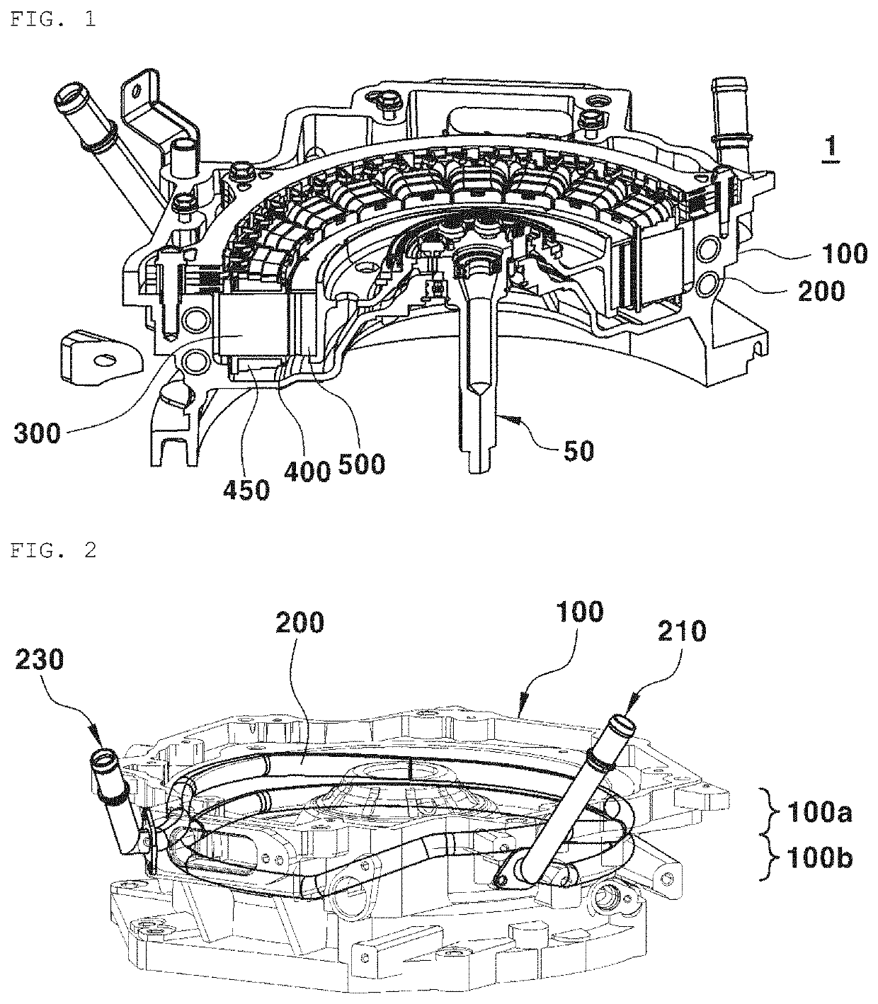
[0017]According to an embodiment of the present disclosure, a stator core is fixed to a motor housing through a press-fitting process, thus eliminating a separate component (existing support ring) for connecting the motor housing to the stator core. As the support ring is eliminated, a process of manufacturing a driving motor can be simplified and the cost of manufacturing the driving motor can be saved.
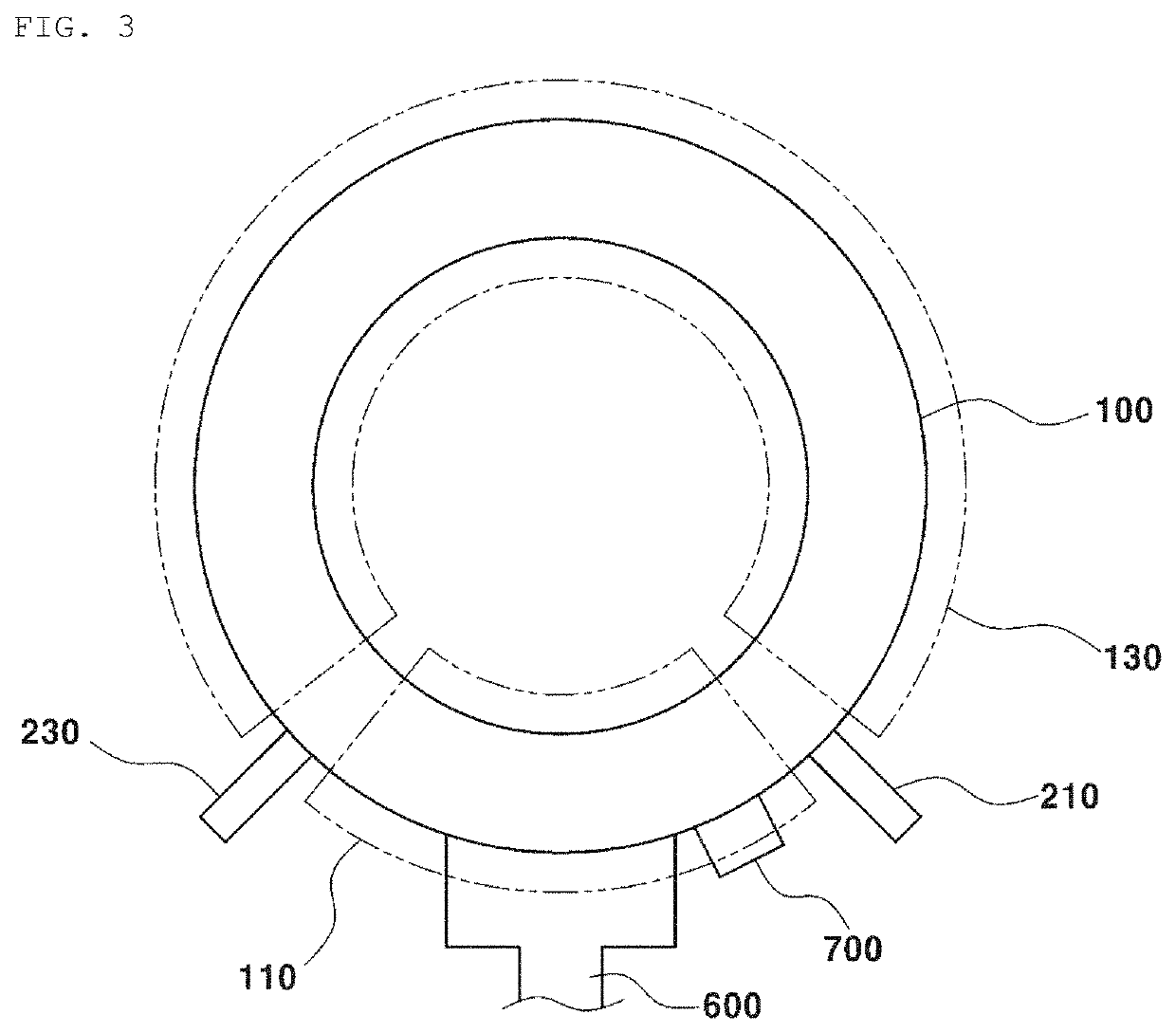
[0018]According to an embodiment of the present disclosure, the position of a cooling pipe may be disposed at a height similar to that of a stator core. In other words, the coolant circulating in the cooling pipe may approach the stator core as close as possible to cool the stator core. Therefore, the efficiency of cooling the stator core can be improved.

Problems solved by technology

This may result in irreversible deterioration of component performance under high-temperature conditions above a certain temperature.
Such deterioration leads to damage to the components and degradation of motor performance.
However, this is problematic in that a process is complicated due to a support-ring coupling process and in that the support ring is additionally required.
Thus, the cost for manufacturing the motor is increased.
Furthermore, the cooling passage between the support ring and the housing is not manufactured in a sealed structure.
As a result, coolant may leak out and thus the performance of the motor may be degraded.

Method used


Image

  • Motor housing with an integrated cooling passage
  • Motor housing with an integrated cooling passage
  • Motor housing with an integrated cooling passage

Examples


Embodiment Construction

[0026]The above and other objects, features, and other advantages of the present disclosure will be more clearly understood from the following detailed description when taken in conjunction with the accompanying drawings. However, the disclosure should not be limited to embodiments set forth herein and may be implemented in a variety of forms. The embodiments described herein are provided to make the disclosure complete and to fully convey the spirit of the disclosure to those having ordinary skill in the art. The disclosure is defined merely by the scope of claims. The same reference numerals are used throughout the drawings to designate the same components.

[0027]The terms “ . . . part”, “ . . . unit”, “ . . . module” and the like described herein may mean a unit for processing at least one function or operation, and they may be implemented in hardware, software or a combination of hardware and software.

[0028]Furthermore, the terms “first”, “second” and the like are used herein to ...


PUM


Abstract

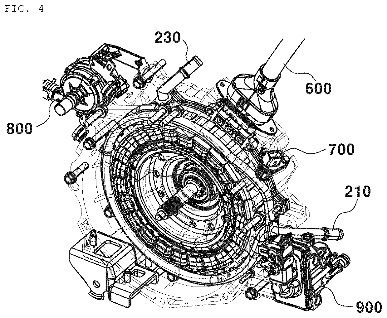
A cooling-channel integrated motor housing includes a motor housing, a plurality of stator cores press-fitted into the motor housing, and a cooling pipe inserted into the motor housing and disposed in a circumferential direction of a circle along which the stator cores are arranged. The 1 cooling pipe is disposed to overlap with the stator cores in a direction perpendicular to a direction in which a rotating shaft of a motor extends.

Description

CROSS REFERENCE TO RELATED APPLICATION[0001]The present application claims priority to Korean Patent Application No. 10-2019-0165710, filed Dec. 12, 2019, the entire contents of which are incorporated herein for all purposes by this reference.BACKGROUND OF THE DISCLOSUREField of the Disclosure[0002]The present disclosure relates to a cooling-passage integrated motor housing, i.e. a motor housing with an integrated cooling passage, in which a motor housing and a cooling pipe are integrally formed.Description of the Related Art[0003]An eco-friendly vehicle is equipped with an electric motor that drives the vehicle by the power of a high-voltage battery. A driving motor is composed of main components to generate output, such as a permanent magnet, a core, or a coil. Due to electric resistance or magnetic resistance generated in the components when a current or a magnetic force flows, heat is generated in the motor. This may result in irreversible deterioration of component performance ...

Claims


Application Information

Patent Timeline
Patent Type & Authority Applications(United States)
IPC IPC(8): H02K9/193H02K5/20H02K1/20
CPCH02K9/193H02K1/20H02K5/20H02K9/19H02K5/203H02K5/225H02K9/225H02K5/02B60K2001/006B60Y2200/90Y02T10/62Y02T10/64
Inventor BAE, SUNG IKHA, JAE WONKIM, DONG JAEJEONG, MYUNG KYULEE, HEE RA
Owner HYUNDAI MOTOR CO LTD
Why Eureka
Try Eureka