Single-sheath microfluidic chip

a microfluidic chip and single-sheath technology, applied in the field of single-sheath microfluidic chip design, can solve the problems of severe volume restrictions, process is often time-consuming, and current separation techniques cannot, for example, produce the desired yield, etc., to achieve the effect of simplifying system complexity, reducing operational costs, and reducing the volume of sheath fluid

Active Publication Date: 2021-07-15
ABS GLOBAL
View PDF1 Cites 1 Cited by
  • Summary
  • Abstract
  • Description
  • Claims
  • Application Information

AI Technical Summary

Benefits of technology

[0013]One of the unique and inventive technical features of the present invention is the physical restriction of the channel geometry at the flow focusing region. Without wishing to limit the invention to any theory or mechanism, it is believed that the technical feature of the present invention advantageously eliminates a second sheath flow structure from the microfluidic device such that the use of a secondary sheath fluid to focus/orient sperm cells becomes unnecessary, thus reducing the volume of sheath fluid used as compared to existing devices that have two focusing regions using sheath fluids for stream compression. This provides an additional benefit of reducing operational costs for equipment and supplies, and further simplifying system complexity. None of the presently known prior reference...

Problems solved by technology

When separating a sample, such as the separation of sperm into viable and motile sperm from non-viable or non-motile sperm, or separation by gender, the process is often a time-consuming task and can have severe volume restrictio...

Method used


Image

  • Single-sheath microfluidic chip
  • Single-sheath microfluidic chip
  • Single-sheath microfluidic chip

Examples


Embodiment Construction

[0038]Before turning to the figures, which illustrate the illustrative embodiments in detail, it should be understood that the present disclosure is not limited to the details or methodology set forth in the description or illustrated in the figures. It should also be understood that the terminology is for the purpose of description only and should not be regarded as limiting. An effort has been made to use the same or like reference numbers throughout the drawings to refer to the same or like parts.

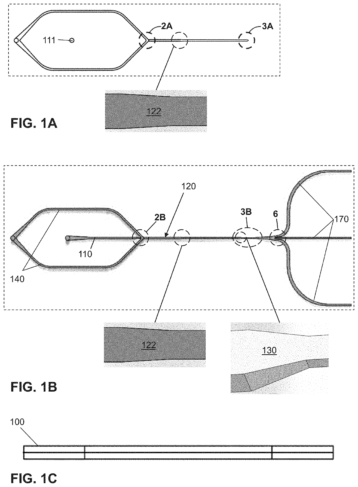
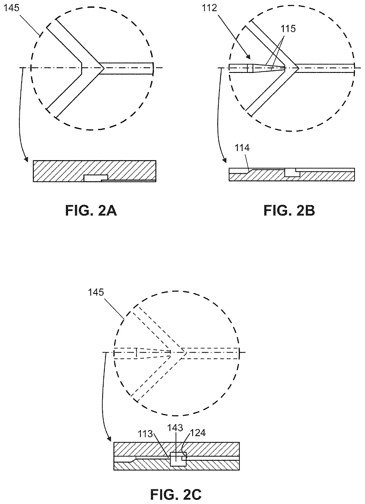
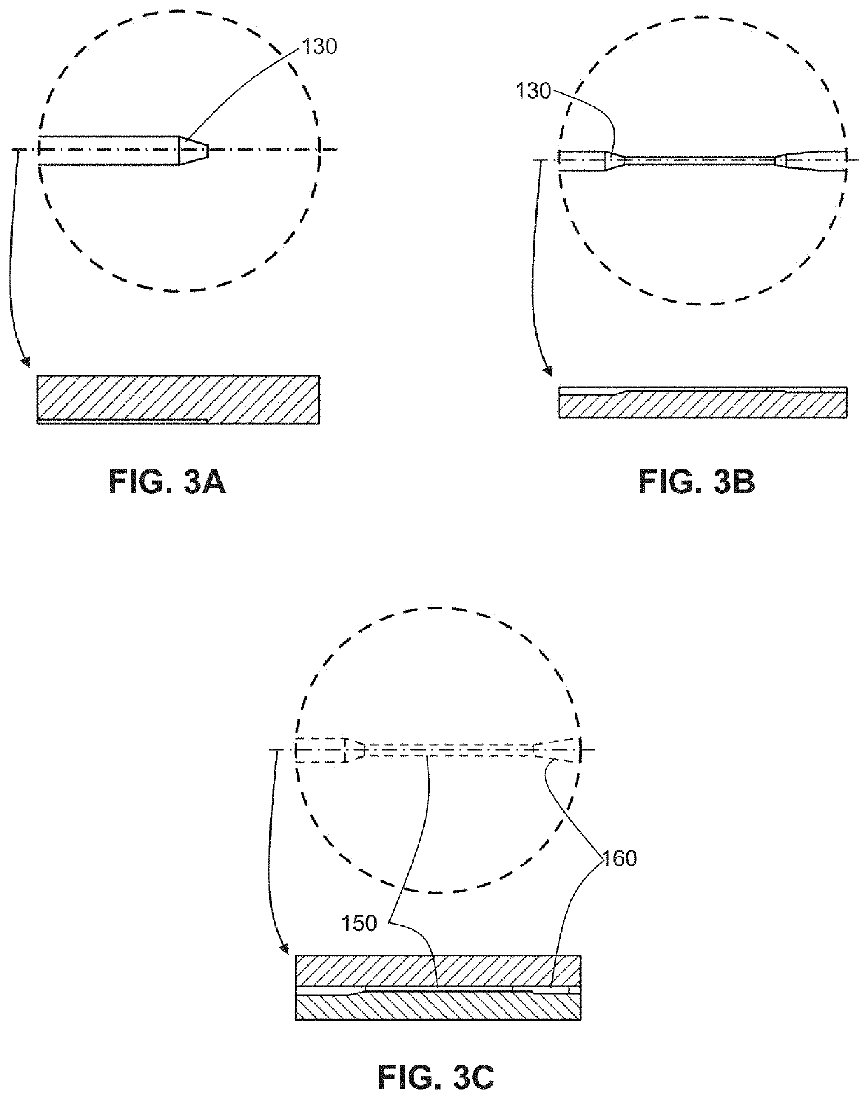
[0039]Following is a list of elements corresponding to a particular element referred to herein:[0040]100 microfluidic chip[0041]110 sample micro-channel[0042]111 inlet of sample micro-channel[0043]112 narrowing region[0044]113 outlet of sample micro-channel[0045]114 bottom surface of narrowing region[0046]115 sidewalls of narrowing region[0047]120 downstream micro-channel[0048]122 constricting portion[0049]124 inlet of downstream micro-channel[0050]125 sidewalls of constricting portion[0...


PUM


Abstract

Microfluidic devices and methods for focusing components in a fluid sample are described herein. The microfluidic devices feature a microfluidic chip having a micro-channel having a constricting portion that narrows in width, and a flow focusing region downstream of the micro-channel. The flow focusing region includes a positively sloping bottom surface that reduces a height of the flow focusing region and sidewalls that taper to reduce a width of the flow focusing region, thereby geometrically constricting the flow focusing region. The devices and methods can be utilized in sex-sorting of sperm cells to improve performance and increase eligibility.

Description

BACKGROUND OF THE INVENTIONField of the Invention[0001]The present invention relates to a microfluidic chip design, in particular, to a microfluidic chip for isolating particles or cellular materials using laminar flow from a single sheath and geometric focusing.Background Art[0002]Microfluidics enables the use of small volumes for preparing and processing samples, such as various particles or cellular materials. When separating a sample, such as the separation of sperm into viable and motile sperm from non-viable or non-motile sperm, or separation by gender, the process is often a time-consuming task and can have severe volume restrictions. Current separation techniques cannot, for example, produce the desired yield, or process volumes of cellular materials in a timely fashion. Furthermore, existing microfluidic devices do not effectively focus or orient the sperm cells.[0003]Hence, there is need for a microfluidic device and separation process utilizing said device that is continu...

Claims


Application Information

Patent Timeline
IPC IPC(8): B01L3/00
CPCB01L3/502776B01L3/502761B01L2300/0858B01L2200/0636B01L2300/0819B01L2200/0647B01L2300/0627B01L2300/06B01L2300/0851
Inventor XIA, ZHENGKAMALAKSHAKURUP, GOPAKUMAR
Owner ABS GLOBAL
Why Eureka
Try Eureka