Devolatilizer design

a devolatilizer and design technology, applied in the field of devolatilizer design, can solve the problems of reducing the effectiveness of fouling of condensers, affecting the efficiency of vacuum condensers, and the typical devo design experiencing high polymer carryover into the vents and eventually into the vacuum condensers

Pending Publication Date: 2021-08-12
DOW GLOBAL TECH LLC
View PDF0 Cites 1 Cited by
  • Summary
  • Abstract
  • Description
  • Claims
  • Application Information

AI Technical Summary

Problems solved by technology

However, typical devo designs experience high polymer carryover into the vents and eventually into the vacuum condensers.
When polymer gets carried over into the vacuum condensers, it fouls the condensers reducing their effectiveness, i.e., the vacuum condensers cannot maintain the level of vacuum inside the devo.

Method used


Image

  • Devolatilizer design
  • Devolatilizer design
  • Devolatilizer design

Examples


Embodiment Construction

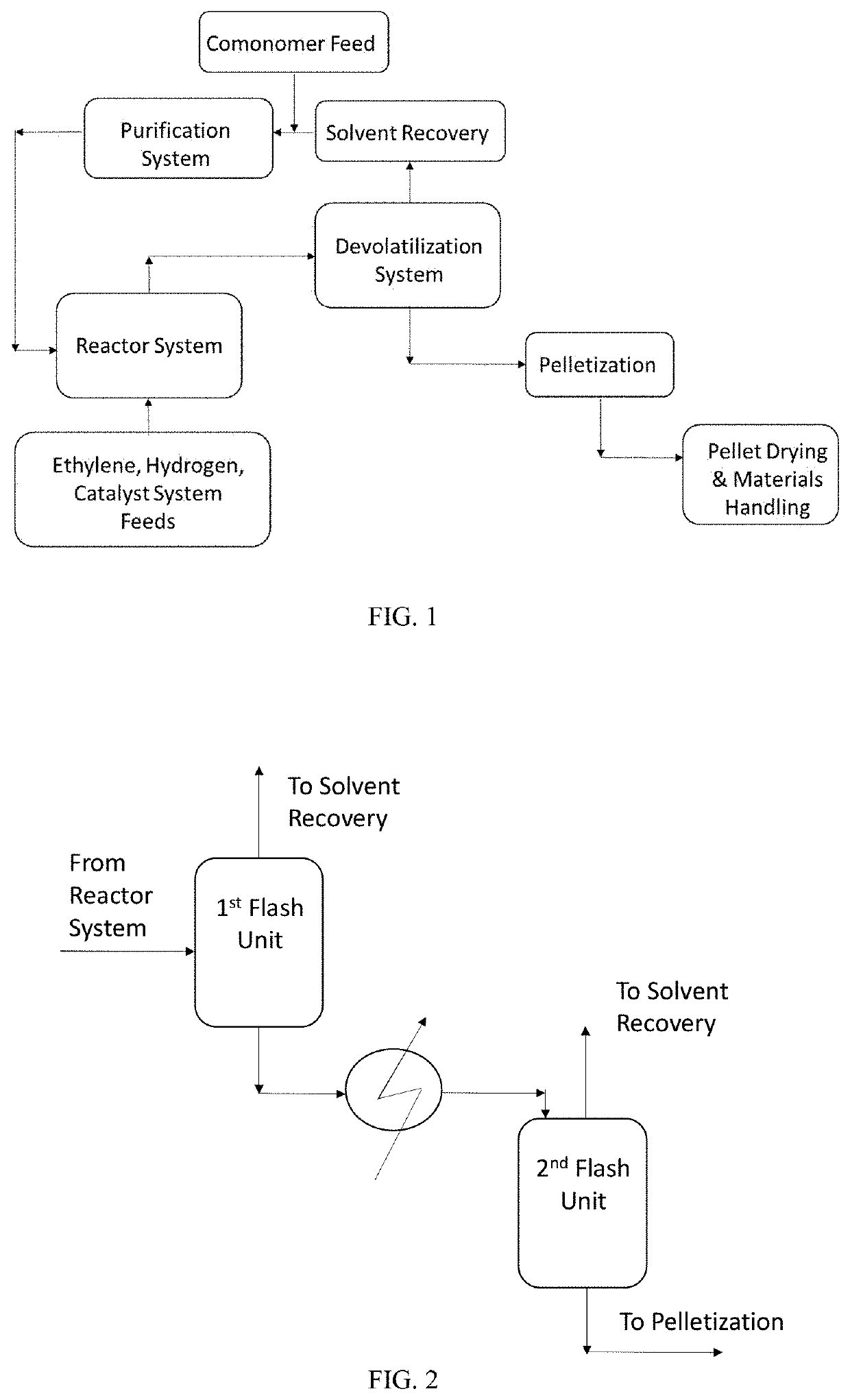
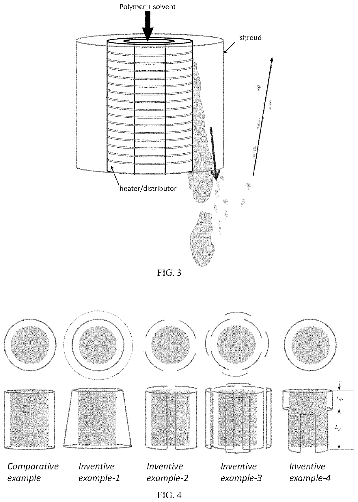
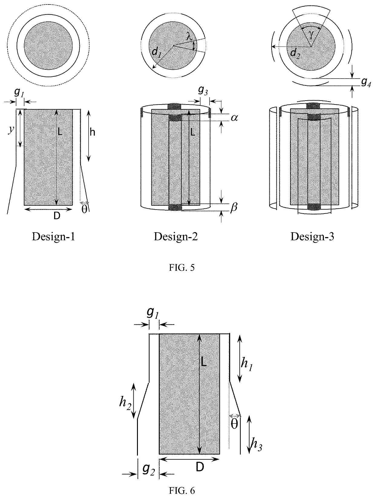
[0018]As discussed above an apparatus is a devolatilizer (devo), as discussed above (see Summary of Invention), is provided.

[0019]The devolatilizer (devo) may comprise two or more embodiments described herein.

[0020]In one embodiment, the polymer-rich solution comprises ≥60 wt %, or ≥70 wt %, or ≥80 wt %, or ≥90 wt %, or ≥95 wt % of the polymer, based on the weight of the polymer-rich solution.

[0021]In one embodiment, the width (w) of the gap varies along the length L.

[0022]In one embodiment, the width (w) of the gap varies continuously along the length L.

[0023]In one embodiment, the width (w) of the gap varies discontinuously along the length L.

[0024]In one embodiment, L is from 10 cm to 200 cm, or from 20 cm to 180 cm, or from 30 cm to 160 cm.

[0025]In one embodiment, for each distance y, the average vertical downward velocity from 1 m / s to 10 m / s, or from 1 m / s to 8 m / s, or from 1 m / s to 6 m / s, or from 1 m / s to 4 m / s.

[0026]In one embodiment, the radial average velocity exiting the ...


PUM

PropertyMeasurementUnit
velocityaaaaaaaaaa
temperatureaaaaaaaaaa
θaaaaaaaaaa

Abstract

A devolatilizer (devo), which operates at a temperature (T) and at a pressure (P), for the separation of at least a portion of a solvent from a polymer-rich solution comprising the solvent and a polymer, and wherein the devolatilizer comprises at least the following components:
    • A) a distributor, a heater, or a heater/distributor combination;
    • B) a shroud (component B) located around some or all of the periphery of component A; and
    • C) a gap (component C) located between the outer surface of component A and the inner surface of component B.

Description

BACKGROUND[0001]For solution polymerization, there is a need for a devolatilization design that will reduce polymer carryover into the vacuum condensers. In a solution polyethylene process, the unreacted ethylene and the solvent is typically removed from the polymer using two flash units, referred to as the devolatilization (devo) tanks. The unreacted ethylene and most of the solvent are removed in the first devo, resulting in a polymer concentration of 80-90 wt %. The rest of the solvent is removed in the second devo. The stream from the first devo is typically heated using a heat exchanger or heater. As the polymer flows through the heater and it heats up, the solvent vaporizes and it phase-separates out of the polymer causing foam formation towards the exit of the heater slots into the second devo tank. The volatiles disengage from the polymer outside the heater, the molten polymer collects at the bottom of the vessel and the vapors are removed through nozzles at the top of the d...

Claims


Application Information

Patent Timeline
Patent Type & Authority Applications(United States)
IPC IPC(8): C08F6/10B01D1/22B01D3/06
CPCC08F6/10B01D3/06B01D1/221C08F6/003B01D3/008C08L23/04
Inventor POLLARD, MARIAKHAN, IRFANDHODAPKAR, SHRIKANTLOPEZ, MARTINYUAN, QUAN
Owner DOW GLOBAL TECH LLC
Why Eureka
Try Eureka