
Magnetometer and method of detecting a magnetic field

a magnetic field and magnetometer technology, applied in the field of magnetometer and magnetic field detection method, can solve the problems of reducing the spin coherence time of each spin, compromising the sensitivity of magnetometer, etc., and achieves high spatial resolution, high spin densities, and the effect of enlarging the range of solid-state electronic spin systems

Active Publication Date: 2021-08-19
UCL BUSINESS PLC
View PDF2 Cites 8 Cited by
  • Summary
  • Abstract
  • Description
  • Claims
  • Application Information

AI Technical Summary

Benefits of technology

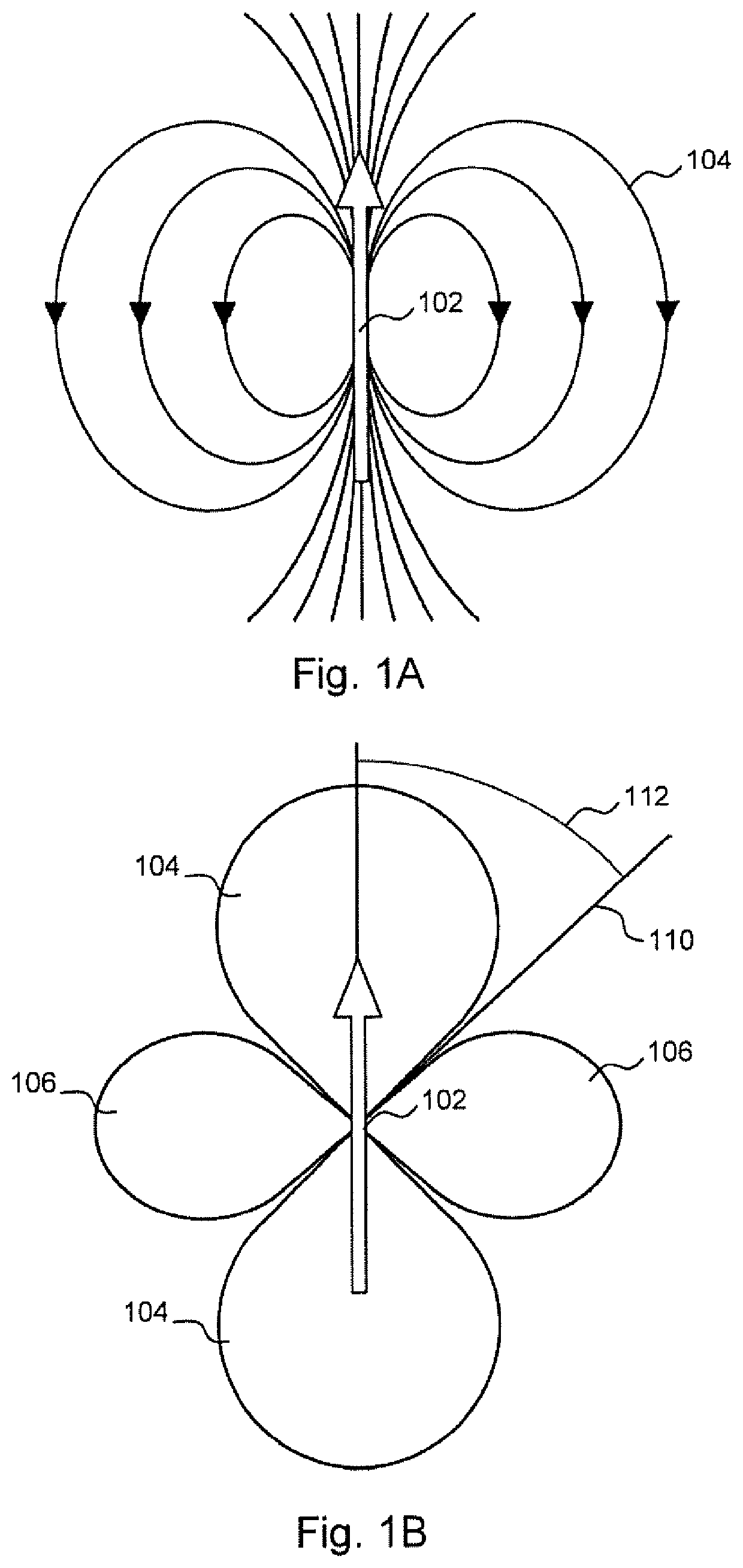
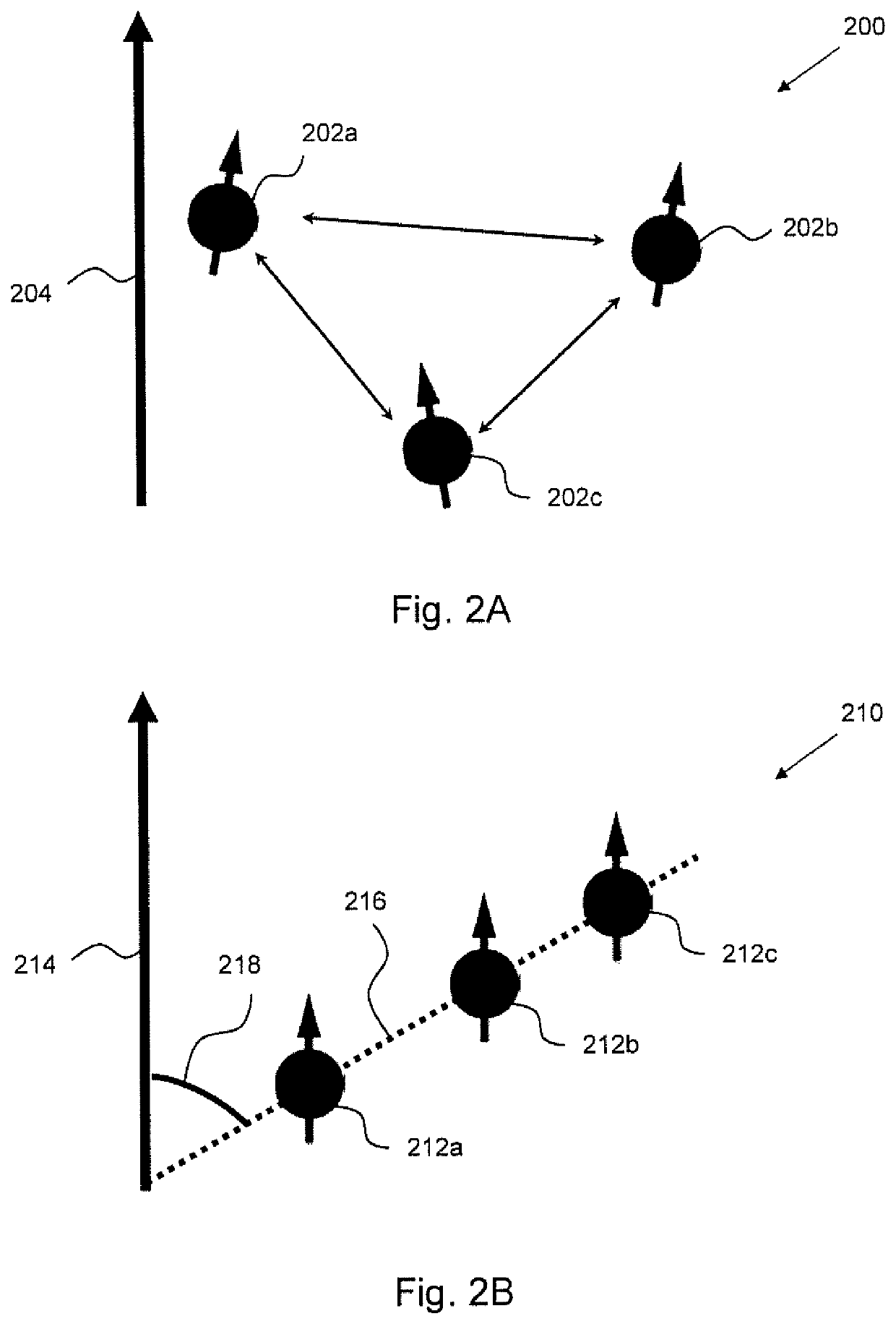
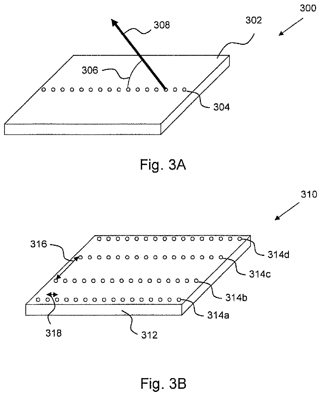
This patent describes a new magnetometer that uses a solid state electronic spin system to detect magnetic fields. The system contains multiple electronic spins that align with an external magnetic field when an alignment stimulus is applied. The spins are organized in groups, each containing multiple spins, which are arranged at an angle to the magnetic field. This arrangement increases the coherence time of the spins, making the magnetometer more sensitive. The method also allows for higher spin densities and the use of smaller and more precise structures for magnetic field detection. The performance of the system can be optimized by minimizing the levels of undesired isotopes. Overall, this new magnetometer offers improved sensitivity and resolution for magnetic field detection.

Problems solved by technology

However, it has been found that magnetometer sensitivity is compromised as the spin density increases.
Magnetometer sensitivity compromise can result from greater magnetic interference from mutual spin-spin interactions and / or from interactions with the solid state lattice, leading to a reduced spin coherence time of each spin.

Method used


Image

  • Magnetometer and method of detecting a magnetic field
  • Magnetometer and method of detecting a magnetic field
  • Magnetometer and method of detecting a magnetic field

Examples


Embodiment Construction

[0022]Solid State Electronic Spin Systems

[0023]Any solid state electronic spin system, including surface and body systems, known or to be developed, can be used in the implementation of the present disclosure.

[0024]Examples of suitable spin systems include molecular spin systems, spin systems based on defects or impurities in inorganic solids, and spin systems based on the electron spins of artificial atoms such as quantum dots.

[0025]Molecular Spin Systems

[0026]In molecular spin systems, the spin is typically localised on a metal ion surrounded by ligands, or delocalised with a region of an organic molecule. In both cases, the solvent environment around the molecule plays a critical role in determining the spin coherence time. Longer coherence times are generally provided by solvents which are essentially free of nuclear spins, such as carbon disulphide (CS2). In particular, a molecular magnet having ligands that are nuclear-spin-free and are soluble in CS2 allowed coherence times o...


PUM

PropertyMeasurementUnit
θaaaaaaaaaa
θaaaaaaaaaa
θaaaaaaaaaa

Abstract

The disclosure concerns a magnetometer for detecting a magnetic field, comprising: a solid state electronic spin system containing a plurality of electronic spins and a solid carrier, wherein the electronic spins are configured to be capable of aligning with an external magnetic field in response to an alignment stimulus; and a detector configured to detect an alignment response of the electronic spins, such that the external magnetic field can be detected; wherein the electronic spins are provided as one or more groups, each group containing a plurality of spins, the plurality of spins in each of the one or more groups being arranged in a line that is angled at an angle Θ with respect to the local direction of the external magnetic field at the said group. Also disclosed is a method for detecting a magnetic field.

Description

TECHNICAL FIELD[0001]The present disclosure relates to a magnetometer and to a method of detecting a magnetic field.BACKGROUND[0002]U.S. Pat. No. 8,947,080 (Lukin et al), the contents of which are incorporated herein by reference, describes a magnetometer which includes a solid state electronic spin system and a detector. The solid state electronic spin system contains a plurality of electronic spins that are disposed at locations within a solid carrier which in that case is a single crystal diamond lattice supported by a suitable support structure within the magnetometer, for example attached to an optical waveguide 610 (see FIG. 6 of U.S. Pat. No. 8,947,080). Furthermore, each electronic spin is substantially free of magnetic interference from the carrier, particularly the remainder of the diamond lattice.[0003]The spins disclosed in U.S. Pat. No. 8,947,080 are nitrogen vacancy (NV) centres within the diamond lattice. An NV centre is a crystallographic defect in the lattice struct...

Claims


Application Information

Patent Timeline
Patent Type & Authority Applications(United States)
IPC IPC(8): G01R33/02
CPCG01R33/02G01R33/24G01R33/60G01N24/10G01R33/30G01R33/032G01R33/1284
Inventor LO, CHEUK CHIWOLFOWICZ, GARYROSS, PHILIPPMORTON, JOHN
Owner UCL BUSINESS PLC
Learn More