Supercharge Your Innovation With Domain-Expert AI Agents!

Method for generating a digital hologram, associated device, holographic display system and computer program

a digital hologram and associated device technology, applied in the field of digital holography, can solve the problems of limiting the possibilities of use, calculating the omnidirectional angular, and consuming a lot of calculation time, and achieve the effect of improving the situation

Active Publication Date: 2021-08-26
FOND B COM
View PDF0 Cites 0 Cited by
  • Summary
  • Abstract
  • Description
  • Claims
  • Application Information

AI Technical Summary

Benefits of technology

The invention aims to create a more straightforward way to see a hologram that offers a quality view of a scene. This is done by storing the angular spectra of objects locally, which allows a head-mounted display to create a hologram in real-time that is adapted to the observer's position.

Problems solved by technology

A first drawback of the proposed method is that it only provides for a single object, which limits its possibilities of use.
A second drawback of this method is that the occultation management is made using a test of intersection between each light ray and the geometry of the scene, which is extremely calculation-time consuming.
A third drawback of this method is that it calculates the omnidirectional angular spectrum at the surface of a sphere sampled by successive subdivisions of a regular icosahedron.
To derive the planar spectrum of the hologram, the extraction of plane waves from this sampling requires the use of a graph travel algorithm to travel through all the vertices of the meshing, which is relatively complex.
A fourth drawback of this method is that the pre-calculation of the omnidirectional angular spectrum of the scene depends on the size of the pixels of the hologram, which prevents the so-calculated omnidirectional angular spectrum to be reusable for holograms having dimensions and resolutions, and hence pixel sizes, different from those which were initially planned.
A fifth drawback of this method is that it restricts the possible positions of the hologram plane, as shown by equation 2 of the document US2016 / 0231706, to a rotation in a plane of the sphere and a translation along one of these rays.
It hence does not allow generating a hologram whose optical axis is not directed towards the center of the object.

Method used


Image

  • Method for generating a digital hologram, associated device, holographic display system and computer program
  • Method for generating a digital hologram, associated device, holographic display system and computer program
  • Method for generating a digital hologram, associated device, holographic display system and computer program

Examples


Embodiment Construction

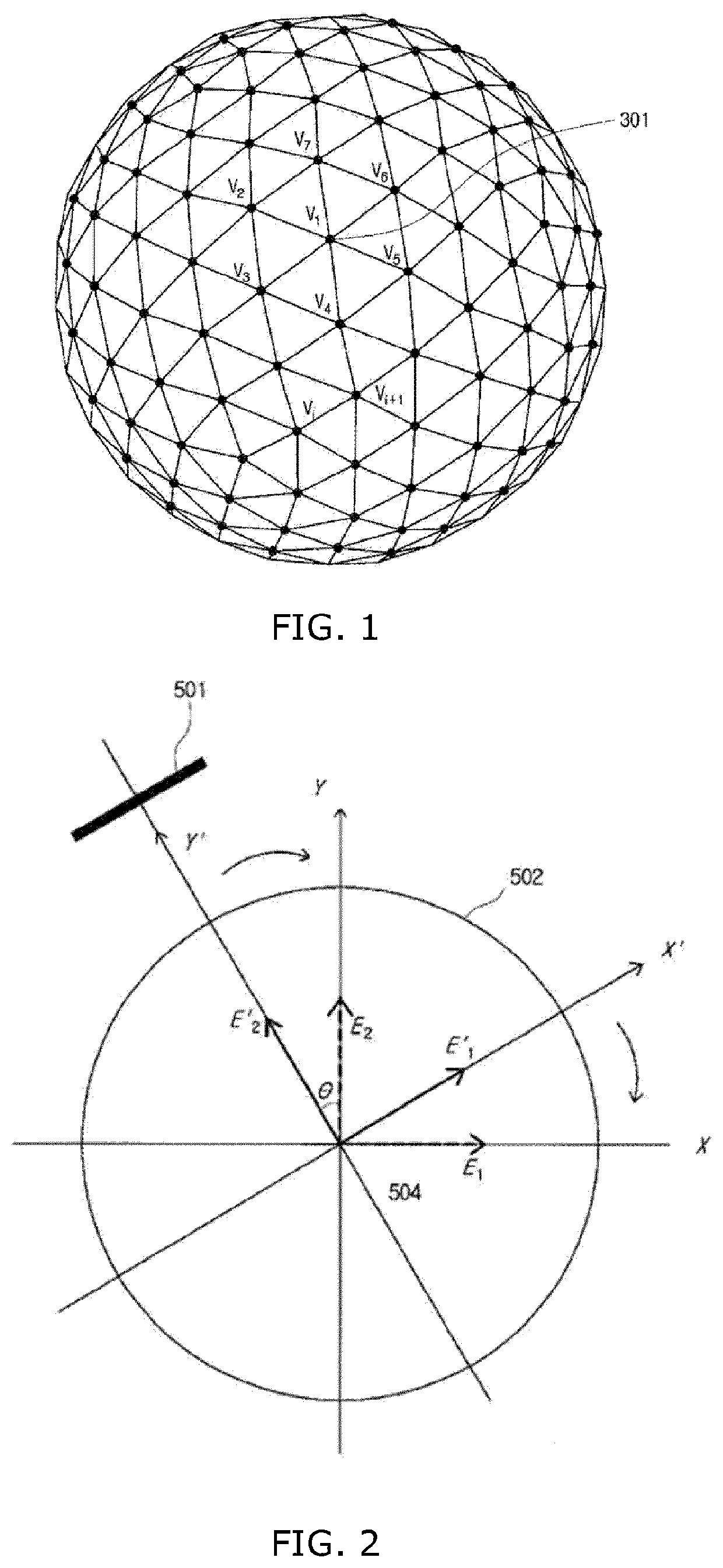
[0073]The general principle of the invention is based on a pre-calculation step, in which the omnidirectional angular spectrum emitted by each object of the scene is calculated at the surface of a geometric solid sampled according to a regular grid. The omnidirectional angular spectrum corresponds to the plane-wave decomposition of the light field emitted by each object. Each plane wave is represented by a frequency coordinate vector corresponding to its direction of propagation and by its complex amplitude. During this pre-calculation step, the occultations of the scene are taken into account for a set of predetermined directions. According to the invention, for a given object, as many angular sub-spectra as directions are calculated. The contributions of each of the sub-spectra associated with the plurality of angular directions are then cumulated to form the angular spectrum of the object.

[0074]Upon reception of a new pose of an observer U, the invention derives a hologram in a p...


PUM


Abstract

Disclosed is a method for generating a digital hologram representing a 3D scene including an object, an object being defined by points and their associated intensity. For each object, a prior step of calculating an “omnidirectional” angular spectrum of the light field emitted by an object in the scene on the surface of a geometric solid centered on the object, a surface of the solid being sampled according to a predetermined grid, a sample of the grid being associated with a vector frequency; for the scene, the following steps: —obtaining a pose of an observer in the world frame of reference; —deriving the hologram from the scene as a function of the pose obtained from the “multidirectional” angular spectra calculated for each object. The step of calculating an angular spectrum of the light field for each object of the scene takes into account predetermined viewing directions.

Description

1. FIELD OF THE INVENTION[0001]The field of the invention is that of digital holography, in particular the generation of a digital hologram from geometric information of a 3D scene.[0002]The invention relates to a method for rapid calculation of a digital hologram and can in particular, but not exclusively, be applied to the real-time rendering of a 3D scene on a head-mounted display in a context of virtual or augmented reality. The holographic head-mounted display immerses the user into a three-dimensional virtual world superimposed or not to the real environment, in which he can move freely. As a function of the movements and displacements of the user, the hologram displayed on the head-mounted display must be recalculated in real-time, which requires a high power of calculation.2. PRESENTATION OF THE PRIOR ART[0003]It is known from the U.S. Patent application, published under No US2016 / 0231706 A1, a method for generating a digital hologram from a pre-calculated omnidirectional an...

Claims


Application Information

Patent Timeline
IPC IPC(8): G03H1/08G02B27/01G03H1/00
CPCG03H1/0808G02B27/0172G02B27/0103G03H2001/0825G02B2027/0174G02B2027/0109G03H2001/0088G03H1/0005G03H2210/30G03H2210/452H04N13/366H04N13/385
Inventor GILLES, ANTONINGIOIA, PATRICK
Owner FOND B COM
Features
  • R&D
  • Intellectual Property
  • Life Sciences
  • Materials
  • Tech Scout
  • Unparalleled Data Quality
  • Higher Quality Content
  • 60% Fewer Hallucinations
Learn More