
Device for staining 3D biopsy tissue

a tissue staining and tissue technology, applied in the field of tissue staining systems, can solve the problems of increasing the risk of false diagnosis, difficult to obtain large tissue samples, and difficulty in identifying the boundaries of small lesions or tumors with the biopsy needle using standard imaging modalities, so as to reduce friction and simplify sample handling

Pending Publication Date: 2021-09-02
KONINKLJIJKE PHILIPS NV
View PDF7 Cites 5 Cited by
  • Summary
  • Abstract
  • Description
  • Claims
  • Application Information

AI Technical Summary

Benefits of technology

The patent text discusses a solution to problems with analyzing tissue samples from biopsies. By measuring the optical spectrum of the surrounding tissue, the method helps determine whether the tumor has been reached, which increases the chances of successful biopsy. Additionally, analyzing the whole intact tissue sample provides valuable information on the structure of the cancer, which can be used to make informed decisions on treating the disease.

Problems solved by technology

While imaging may provide coarse guidance of the needle towards the region of interest, it is often challenging to identify precisely the boundaries of small lesions or tumors with the biopsy needle using standard imaging modalities.
As a consequence, biopsies are often taken at the wrong location, which increases the risk of false diagnoses.
With these biopsies it is often not possible to obtain large tissue samples, with sufficient material to perform all necessary analyses.
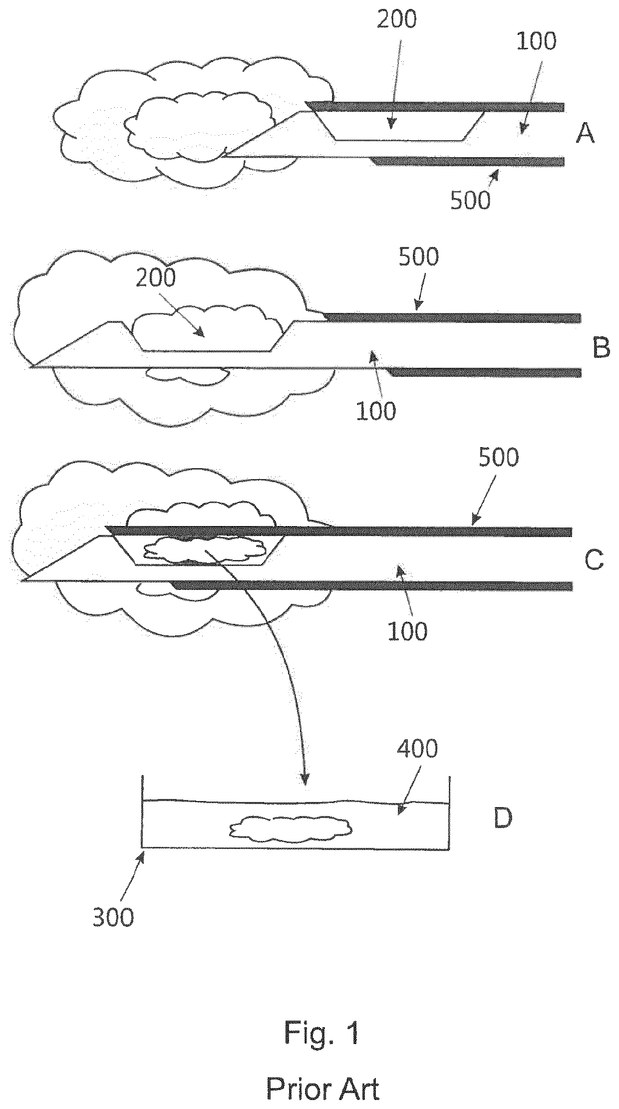
Furthermore, it is a problem that typically staining of a 3D tissue sample, i.e. of a not-sliced sample, takes comparatively long as staining occurs through diffusion, for example in a set up as shown at the bottom of FIG. 1, with the tissue sample 200 taken out of the biopsy needle shaft 100 and located in an open container 300 filled with staining fluid 400.

Method used


Image

  • Device for staining 3D biopsy tissue
  • Device for staining 3D biopsy tissue
  • Device for staining 3D biopsy tissue

Examples


Embodiment Construction

[0060]In FIG. 4, embodiments of a biopsy tube 20 and a tube shaft 30 are shown. The biopsy tube 20 is substantially formed as a hollow cylinder with first and second ends each having a straight edge. In this embodiment, the first end 22 is formed with an angle of 90° relative to the longitudinal axis 26, i.e. substantially perpendicular to the longitudinal axis. The second end 24 is formed with an inclined angle relative to the longitudinal axis 26, wherein this angle may be in the range between 45° and 65°, for example 55°. It will be understood that the angles at the ends of the biopsy tube may be adapted to fit to inclined surfaces of a notch formed in a main shaft of a biopsy device, as described in detail below. For example, the length of such a biopsy tube may be 14 mm+ / −5 mm and an outer diameter may be 2 mm, whereas an inner diameter of a channel 28 which extends through the cylinder, may be between 1.4 and 1.6 mm. The biopsy tube may be made of glass or from a hard and tran...


PUM

PropertyMeasurementUnit
pressureaaaaaaaaaa
pressureaaaaaaaaaa
pressureaaaaaaaaaa

Abstract

A method and system for processing a 3D tissue sample is provided, comprising the steps of receiving a tube with an inner space and two open ends, wherein the tube is configured to retain the 3D tissue sample in the inner space, arranging the tube so that one of the two open ends of the tube is located at a fluid channel, and forcing or actively pressing a tissue processing agent through the fluid channel and into the tube so that the tissue processing agent passes through the tissue.

Description

FIELD OF THE INVENTION[0001]The invention generally relates to a system for staining tissue in its 3D shape as obtained by a biopsy. Particularly, the invention relates to a device for staining biopsy sample accommodated in a biopsy tube maintaining the integrity of an extracted tissue volume.BACKGROUND OF THE INVENTION[0002]For the proper analysis of tumours and defining the appropriate treatment detailed information on a tumour may be needed. First the presence and position of a potential tumour may be identified through medical imaging.[0003]Subsequently a biopsy may be taken to assess whether or not the lesion is benign or malignant through pathology. An exemplary workflow for obtaining a biopsy is depicted in the upper part of FIG. 1. For positioning the biopsy device (usually a needle with a shaft 100 having a lateral recess 200, and an outer tubular member 500) accurately in the suspicious tissue, the correct location is commonly determined using image guidance such as Ultras...

Claims


Application Information

Patent Timeline
Patent Type & Authority Applications(United States)
IPC IPC(8): G01N1/31A61B10/00A61B10/02G01N21/11G01N21/05
CPCG01N1/31A61B10/0096A61B10/0283G01N2021/052G01N21/11G01N21/05A61B10/0275A61B10/04G01N1/30
Inventor VAN DER ZAAG, PIETER JANVULDERS, ROLAND CORNELIS MARTINUSCLOUT, DANIELLE ELISA WILLEMINEVAN EEMEREN, JOHANNES THEODORUS WILHELMUS MARIAVAN DE STOLPE, ANJA
Owner KONINKLJIJKE PHILIPS NV
Learn More