Gas Saturation of Liquids with Application to Dissolved Gas Flotation and Supplying Dissolved Gases to Downstream Processes and Water Treatment

a technology of dissolved gas and liquid, applied in water/sewage treatment, specific water treatment objectives, transportation and packaging, etc., can solve the problems of inefficiency in gas transfer, and large amount of gas bubbles in the plunger, so as to reduce the water weight of the vessel

Active Publication Date: 2021-09-16
FUEL TECH
View PDF4 Cites 0 Cited by
  • Summary
  • Abstract
  • Description
  • Claims
  • Application Information

AI Technical Summary

Benefits of technology

[0029]FIG. 6 shows calculated data derived from Stokes' Law and the results from the computational fluid dynamics modeling illustrated in FIG. 5. These results are also relevant to and further described in Example 4.
[0070]FIG. 4 schematically illustrates an alternate exemplary design of plunging-jet saturator unit according to the invention. In this embodiment, a vessel 414 is shown and may be substituted for the vessel 14 shown in FIG. 3. The lower portion 414b of the chamber is wider than the upper portion 414u, with a diameter increase in some embodiments from 50 to 300% between the upper and lower portions. Employing a bottom section diameter larger than the top section reduces the superficial liquid velocity in this section to prevent the escape of bubbles larger than a given size. This is calculated and designed by comparing bubble size rise velocity according to Stokes' Law with the lower superficial liquid velocity that comes with a wider vessel diameter in the quiescent zone. Variations can be more or less extreme as needed to limit adverse effects of consequences of bubbles escaping. Internal structures may be utilized to condition the flow toward uniformity across the cross-section. This embodiment is just one of several possible alternative vessel geometries or features that provide a bubble limiting functionality. Another design would employ a conical, or even spherical, bottom section. Designs of this nature could reduce the water weight of the vessel compared to the embodiment of FIG. 4.
[0071]FIG. 5 shows computational fluid dynamics modeling results for the lower portion of one realization of the saturator design type described above. These results are relevant to and further described in Example 4.
[0073]The inventors performed experiments to ascertain the combination of design features that demonstrate the advantages of the present invention. A trailered plunging jet saturation unit as depicted in FIG. 1 was designed and evaluated according to the performance features described in the Definitions. Referring to the saturator described more specifically in FIG. 3, parameters directly varied during experimentation included the geometric profile and diameter of nozzle 16, the tank liquid surface level 26, the liquid flow from supply line 10, gas flow from supply line 22, and the operating pressure of vessel 14. Parameters indirectly varied include the superficial liquid velocity VB, the length of the quiescent zone below line 28, and operational dimensions h and d via altering the tank liquid volume and liquid throughput.

Problems solved by technology

Inefficiency in gas transfer occurs when bubbles rise and escape the surface before imparting their gas to the liquid, and is generally exacerbated when the submerged equipment deteriorates and affects feed flow and bubble size control.
Pressurized plunging jet contactors are common practice as reactors, but are notably absent in practice as saturators.
Nevertheless, despite their apparent advantage in lower power demand, plunging jet systems are not used in pressurized saturators to dissolve gas into a liquid for downstream processes.
One reason for this anomaly is that, while requiring less power usage, plunging jets have a downside that is counter to the desired end product.
Plunging jets for gas transfer produce copious amounts of gas bubbles that are undesired in the exiting stream of a saturator.
Such bubbles represent a serious inefficiency if allowed to exit the saturator where the desired product is dissolved gas.
The prior art for plunging jet systems has not been fully developed to demonstrate their adaptation to the goal of a pressurized, single-pass saturator that minimizes energy use while maximizing the dissolved content of gas in the processed liquid while also simultaneously limiting undissolved gas content exiting the device in either size of escaping bubbles or total undissolved gas volume.
Additionally, the technology of plunging jet systems has not been developed sufficiently to fully take advantage of the lowered energy consumption required by a plunging jet system for gas transfer to produce the desired gas-laden liquid as the end product.
In particular, we note that current designs do not employ vessel designs that can effectively limit the size and number of bubbles escaping the saturator while producing a liquid substantially saturated with dissolved gas.
In addition, current designs do not employ controls that assure operation in a manner to optimize the power to outperform existing spray-type saturator solutions.

Method used


Image

  • Gas Saturation of Liquids with Application to Dissolved Gas Flotation and Supplying Dissolved Gases to Downstream Processes and Water Treatment
  • Gas Saturation of Liquids with Application to Dissolved Gas Flotation and Supplying Dissolved Gases to Downstream Processes and Water Treatment
  • Gas Saturation of Liquids with Application to Dissolved Gas Flotation and Supplying Dissolved Gases to Downstream Processes and Water Treatment

Examples


example 1

[0074]In a first example of results, a ⅜″ converging water nozzle was mounted in a pressure vessel of approximately 50 inches in total height. The vessel was operated using water as the liquid and oxygen as the dissolving gas. Table 1 shows recorded data and Table 2 shows corresponding calculated performance data including Infusion Efficiency and Specific Power Use. The intermediate calculation of the kH factor is known in the art of applying Henry's Law to a given set of conditions.

TABLE 1Primary Recorded Data for Example 1Liq. FlowO2 FlowPump OutletMeterMeterInlet TTank Digital % Levelpsigpmlb / hr° C.Pressure psiTankGauge21.0710.93102985032219.039.9103025032016.678.71103055032013.357103055031511.125.561030250307

TABLE 2Calculated Data for Example 1kH for Henry's LawHenry's LawInfusionNozzleSpecific Power UseO2 Calculatedat Avg Tmg / LEfficiencyDPWater HPHP permg per L of Watergram / L-psikH at Avg T(kH at Temp)psiHPlb / hr O21036.110.0037014471134.2792591.34481243.9560.361941039.070.00370...

example 2

[0075]An example of the non-obvious optimization of the plunging jet saturator for minimum specific power use while simultaneously maximizing dissolved gas delivery, the same system was tested with four water nozzles of various diameters at nominally 250 psi tank operating pressure. Results, shown in Table 3, demonstrate that the ⅜″ nozzle and the ½″ nozzle have nearly identical specific power use for the tested conditions. The ¾″ nozzle, while having a low pressure drop, produced a lower infusion efficiency percentage and the lowest volumetric mass transfer coefficient, kLa. The smallest nozzle, while producing the highest infusion efficiency, produced an unacceptable specific power use because of the pressure drop across the nozzle. In these results, the volumetric mass transfer coefficient, kLa, is calculated by knowing the working tank water volume and throughput to calculate a residence time in the vessel and then employing the infusion efficiency calculation demonstrated above...

example 3

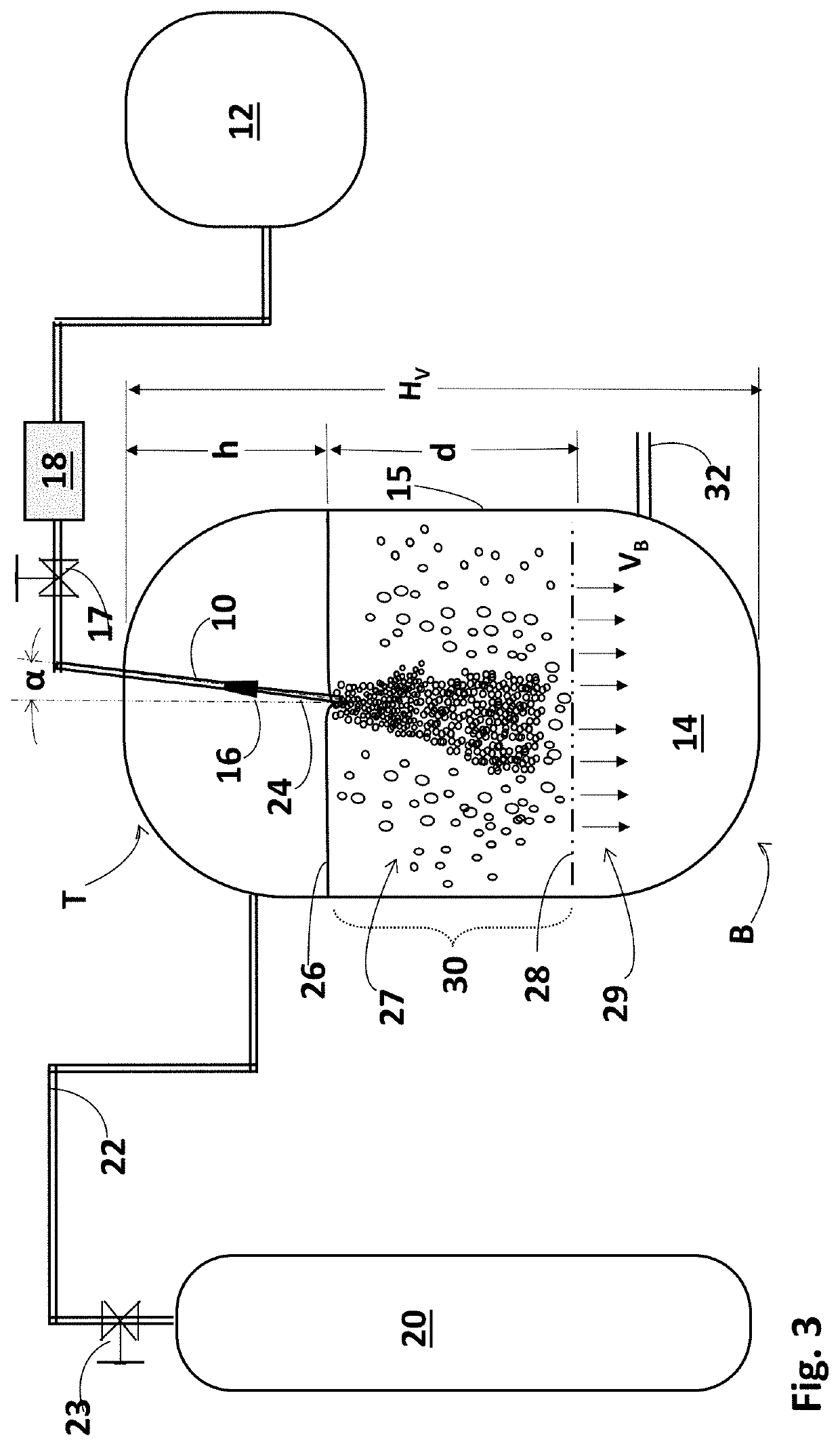
[0078]The indication of an undesirable shift from dissolved gas content to undissolved gas content in the saturator effluent with changing operational conditions is illustrated in the data in Table 4. For this example, a reduction in the quiescent zone length was achieved by dropping the water level (%) in the vessel until bubbles began to encroach on outlet line 32. This demonstrated the importance of establishing a clear quiescent zone length below the turbulent plunge zone. In the data shown, water and oxygen flow are remarkably steady between 47% to 50% tank level. Beyond this point, at lower tank levels and therefore reduced length of quiescent zone, the water flow begins to drop as undissolved oxygen gas displaces the water rather than becomes dissolved in the water. The crossover of the water flow decreasing and the gas flow increasing for a given tank pressure operating condition is a clear indication of an unwanted increase in undissolved gas content in the effluent of the ...


PUM

PropertyMeasurementUnit
pressureaaaaaaaaaa
velocityaaaaaaaaaa
angleaaaaaaaaaa

Abstract

The description relates to methods and apparatus that enable the efficient introduction of gases like air, oxygen and ozone into aqueous liquids. Gases are introduced into liquids for making that gas chemically or biologically available at a minimum energy expenditure. Impinging jets of liquid are directed into a pressurized saturation vessel having a gas-filled headspace and a saturation zone below the surface of the liquid at a velocity sufficient to create a turbulent impact and plunge zone. The resulting turbulence and mixing of gas and liquid in that zone under pressure, causes the gas to be driven into the liquid in the vessel and breaks up the gas and the liquid into a churning flow and creates a large number of bubbles. The resulting gas-enriched liquid is discharged from the vessel at an outlet to ensure a minimum of bubbles in the gas-enriched liquid.

Description

CROSS REFERENCE TO RELATED APPLICATIONS[0001]This application is a regular filing claiming priority to U.S. Provisional Patent Application Ser. 62 / 988,049, filed Mar. 11, 2020, by inventors Ronald A. Lau, et al., the disclosure of which is incorporated herein in its entirety.FIELD OF THE INVENTION[0002]The invention addresses significant problems with the prior art in efficiently dissolving gases in liquids while simultaneously controlling undissolved gas content in an exit stream, with applications for water treatment or other downstream processes typically fed by a gas saturator device.[0003]The invention is specific to gas saturation of liquids in a single-pass, continuously flowing process and device feeding gas-laden liquid to an end-use in which the gas-laden liquid feed is pressurized and undissolved gas content is both minimized and controlled.[0004]In all embodiments the goal is to minimize energy use while maximizing the dissolved content of gas in the processed liquid whi...

Claims


Application Information

Patent Timeline
Patent Type & Authority Applications(United States)
IPC IPC(8): B01F3/04
CPCB01F3/04751C02F1/74B01F3/04836C02F2303/02C02F2301/024C02F1/78C02F1/24C02F1/5245C02F2201/002B01F23/23413B01F23/2368B01F25/20B01F25/53B01F33/5023B01F33/71B01F23/23412B01F23/2376B01F23/237611B01F23/237612B01F23/237613B01F23/2132
Inventor LAU, RONALD A.RINGEL, KAREN L.
Owner FUEL TECH
Why Eureka
Try Eureka