
Surface light source

Active Publication Date: 2021-09-16
SHENZHEN XIANGYOU TECH CO LTD
View PDF0 Cites 0 Cited by
  • Summary
  • Abstract
  • Description
  • Claims
  • Application Information

AI Technical Summary

Benefits of technology

The patent text describes a new design for an optical plate used in display panels. The quantum layer is located in the optical plate, which increases the color expression of the display panels and improves the color gamut level. The design also allows for thinning and miniaturization of the optical plate. A gap between the quantum layer and the side wall of the groove improves the optical coupling effect, resulting in improved light emission. A reflective layer is also included to improve light emission uniformity. The barrier layer includes a plurality of microsphere structures and blind holes to enhance light emission uniformity. The patent aims to improve the performance and quality of optical plates used in display panels.

Problems solved by technology

As a result, a thickness of surface light source module will be increased, which is not capable of facilitating thinning of a display screen.
Moreover, a color gamut level of the surface light source obtained by the above structure is not ideal and still needs to be improved.

Method used


Image

  • Surface light source
  • Surface light source
  • Surface light source

Examples


Embodiment Construction

[0022]The technical solutions in the embodiments of the disclosure will be described clearly and completely hereinafter with reference to the drawings in the embodiment of the disclosure. It is clear that the described embodiments are only a part of embodiments of the disclosure, not all of the embodiments of the present disclosure. Based on the embodiments of the disclosure, other embodiments obtained by the person of ordinary skill in the art without creative labor all fall within the scope of the disclosure.

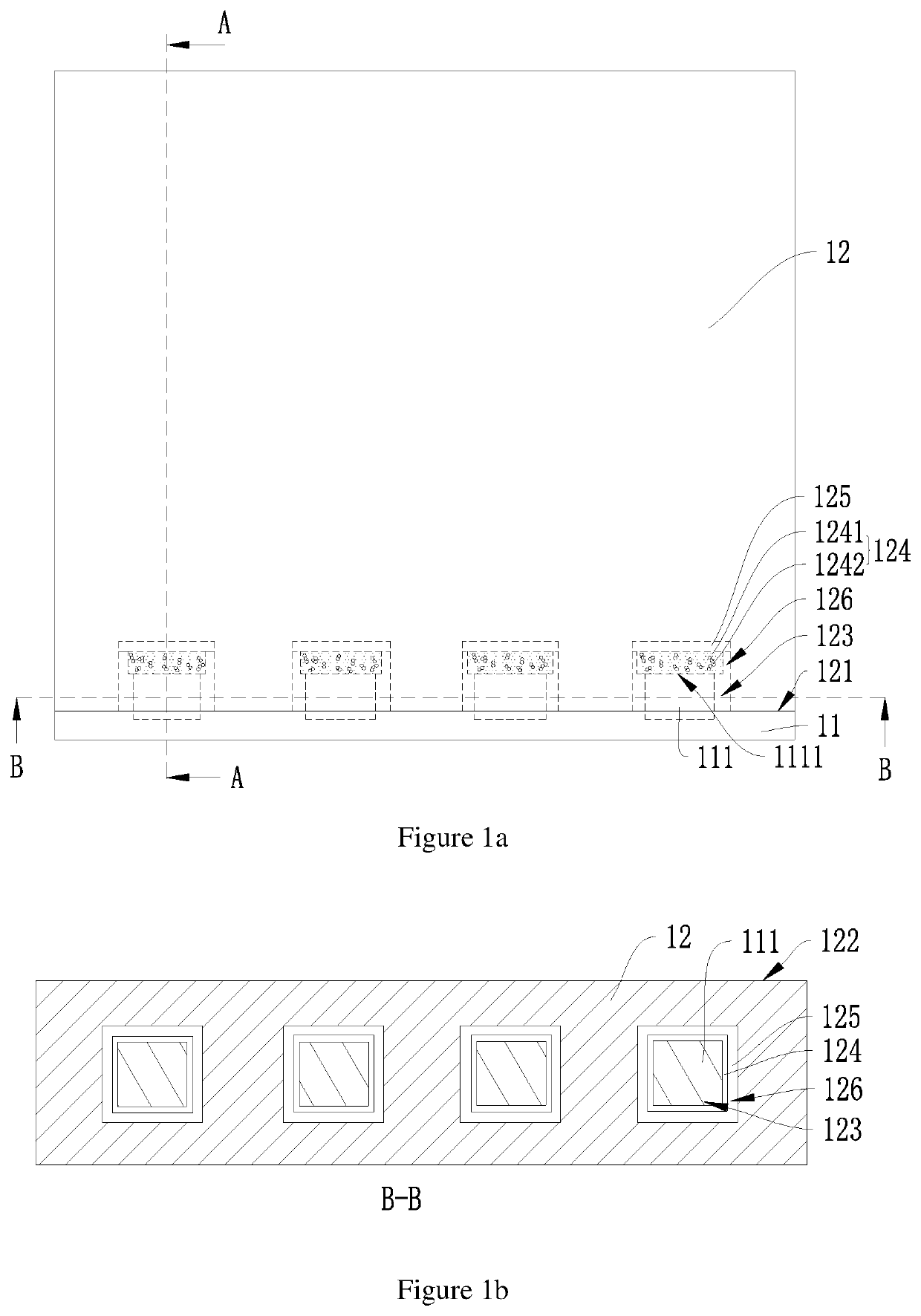
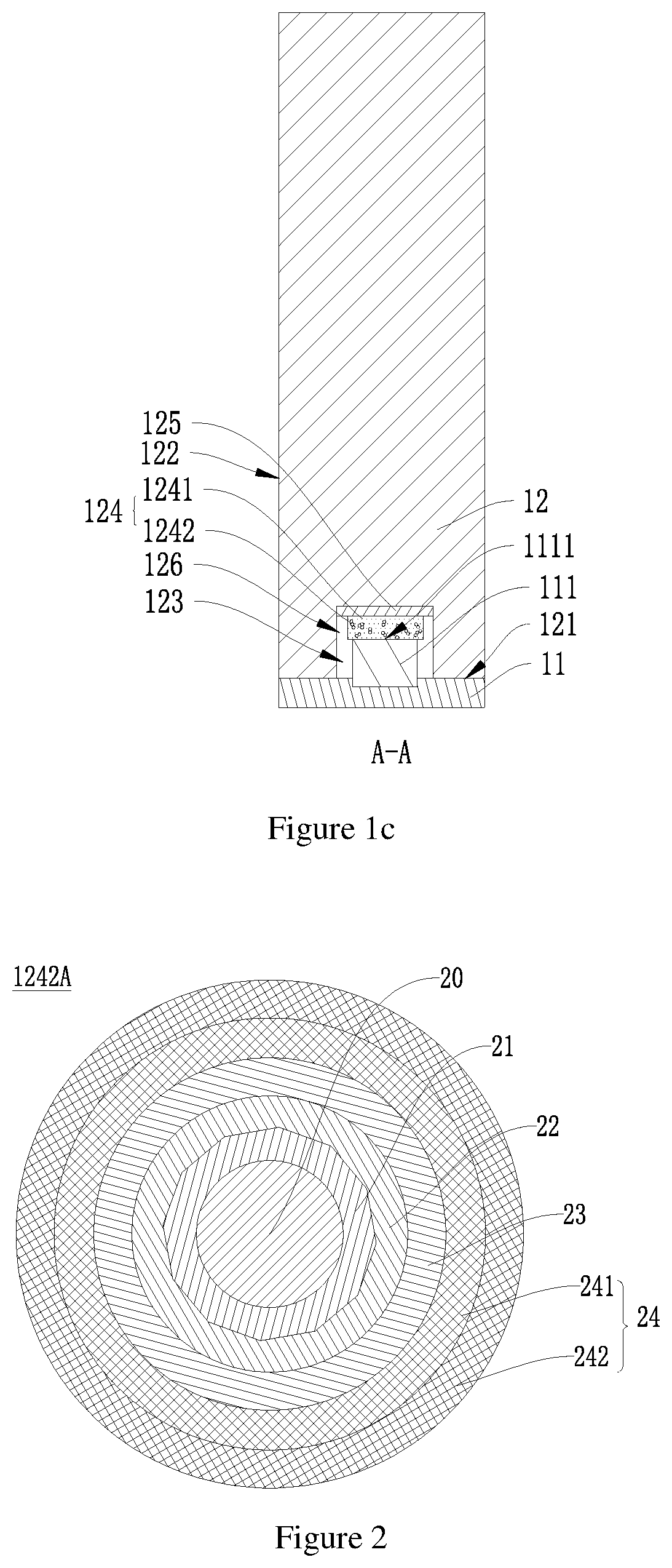
[0023]FIG. 1a is a schematic structural diagram of a surface light source 10 according to an embodiment of the disclosure. FIG. 1b and FIG. 1c respectively correspond to cross-sectional view diagrams taken along lines B-B and A-A in FIG. 1a.

[0024]Specifically, as shown in FIGS. 1a, 1b, and 1c, the surface light source 10 includes a light emitting unit 11 and an optical plate 12. The optical plate 12 has a light input surface 121 and a light output surface 122, and the light i...


PUM


Abstract

A surface light source includes a light emitting unit and an optical plate. The optical plate has a light input surface and a light output surface. A side of the optical plate where the light input surface is located have grooves arranged thereon and spaced from one another. A quantum layer is arranged in each of the grooves and includes a colloid and multiple quantum dot nanostructures dispersed in the colloid. Each the quantum dot nanostructure includes an inner core, a ligand layer, a hydrophobic layer, an encapsulation layer and a barrier layer. The light emitting unit includes light sources respectively arranged in the grooves, and a light emitting surface of each the light source is close to the quantum layer so that at least a part of the light rays emitted from the light source is struck onto the quantum layer.

Description

FIELD OF THE DISCLOSURE[0001]The disclosure relates to the technical field of light source, and in particular to a surface light source.BACKGROUND OF THE DISCLOSURE[0002]Nowadays, higher and higher requirements are required for a surface light source module. On the one hand, it is required to emit light evenly and have a good color gamut; on the other hand, it is required to be thin and light enough. At present, a common method is to place a dot matrix composed of LEDs on a bottom surface of an outer frame of the surface light module, with a light emitting surface of the surface light module facing a diffusion plate. The diffusion plate diffuses light, thus an LED point light source is changed into a relatively uniform surface light source. However, in order to obtain an uniform visual effect, it is necessary to increase a density of the LED dot matrix or increase a space between diffuser plate and each LED. As a result, a thickness of surface light source module will be increased, ...

Claims


Application Information

Patent Timeline
IPC IPC(8): H01L33/06H01L33/32H01L33/52H01L33/10H01L33/34
CPCH01L33/06H01L33/32H01L33/34H01L33/10H01L33/52G02B6/0021G02B6/0031G02B6/0068H01L25/0753H01L33/502H01L33/58
Inventor WU, YUPINGLIU, YUE
Owner SHENZHEN XIANGYOU TECH CO LTD
Learn More