Circuit for processing a wake-up signal

a wake-up signal and circuit technology, applied in the field of circuits for processing wake-up signals, can solve the problems of inability to switch off or deactivate circuits, or require additional protective elements, and achieve the effect of low current consumption and high input resistan

Pending Publication Date: 2021-09-23
ROBERT BOSCH GMBH
View PDF1 Cites 2 Cited by
  • Summary
  • Abstract
  • Description
  • Claims
  • Application Information

AI Technical Summary

Benefits of technology

[0004]A circuit for processing a wake-up signal in accordance with an example embodiment of the present invention may have the advantage that through the use of a multi-channel, integrated comparator circuit, a discrete input circuit and a switchable discrete constant voltage source, input parameters of the circuit, e.g., an input impedance, and criteria for evaluating the applied wake-up signal are easily able to be adjusted by varying the component values in the input circuit and / or in the constant voltage source. Moreover, these input parameters and criteria for use in motor vehicles are able to be specified very precisely and in a stable manner across a wide voltage and temperature range. This is made possible by the high input resistance of the multi-channel integrated comparator circuit by which a high-resistance decoupling of the line of the wake-up signal from the rest of the circuit is achievable. A very broad spectrum of customer specifications is able to be covered in this way without having to revise the layout of the circuit. In addition, the voltage supply of the constant voltage source can be connected only if a wake-up signal is actually applied. Embodiments of the circuit for processing a wake-up signal according to the present invention are therefore completely inactive in the no-load state except for the multi-channel, integrated comparator circuit and are thus characterized by a very low current consumption suitable for permanently supplied systems. The use of the multi-channel, integrated comparator circuit allows for a relatively compact design of the circuit because only a few external components are necessary. The use of a permanently active and controlled voltage supply and a clock source is therefore not required.

Problems solved by technology

In addition, these circuits are unable to be switched off or deactivated or require additional protective elements in order to be directly connectable to wake-up lines in a vehicle.

Method used


Image

  • Circuit for processing a wake-up signal
  • Circuit for processing a wake-up signal

Examples


Embodiment Construction

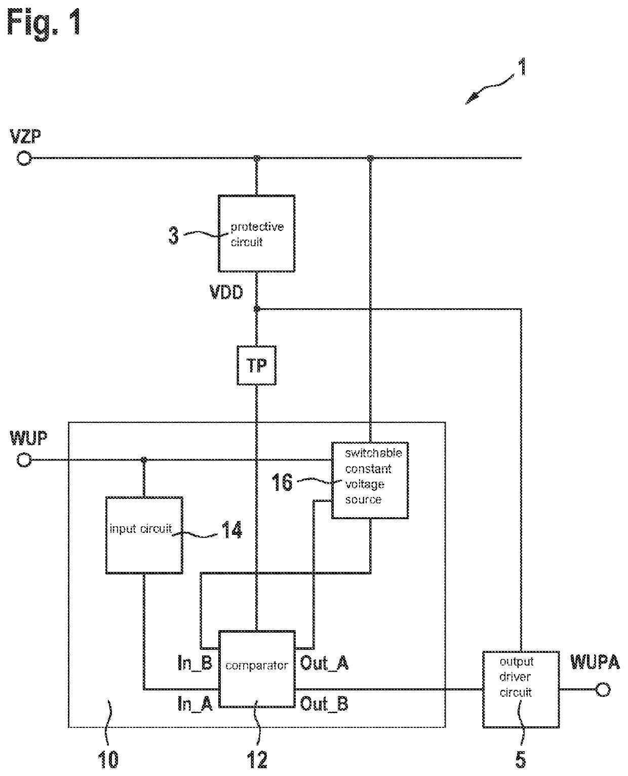
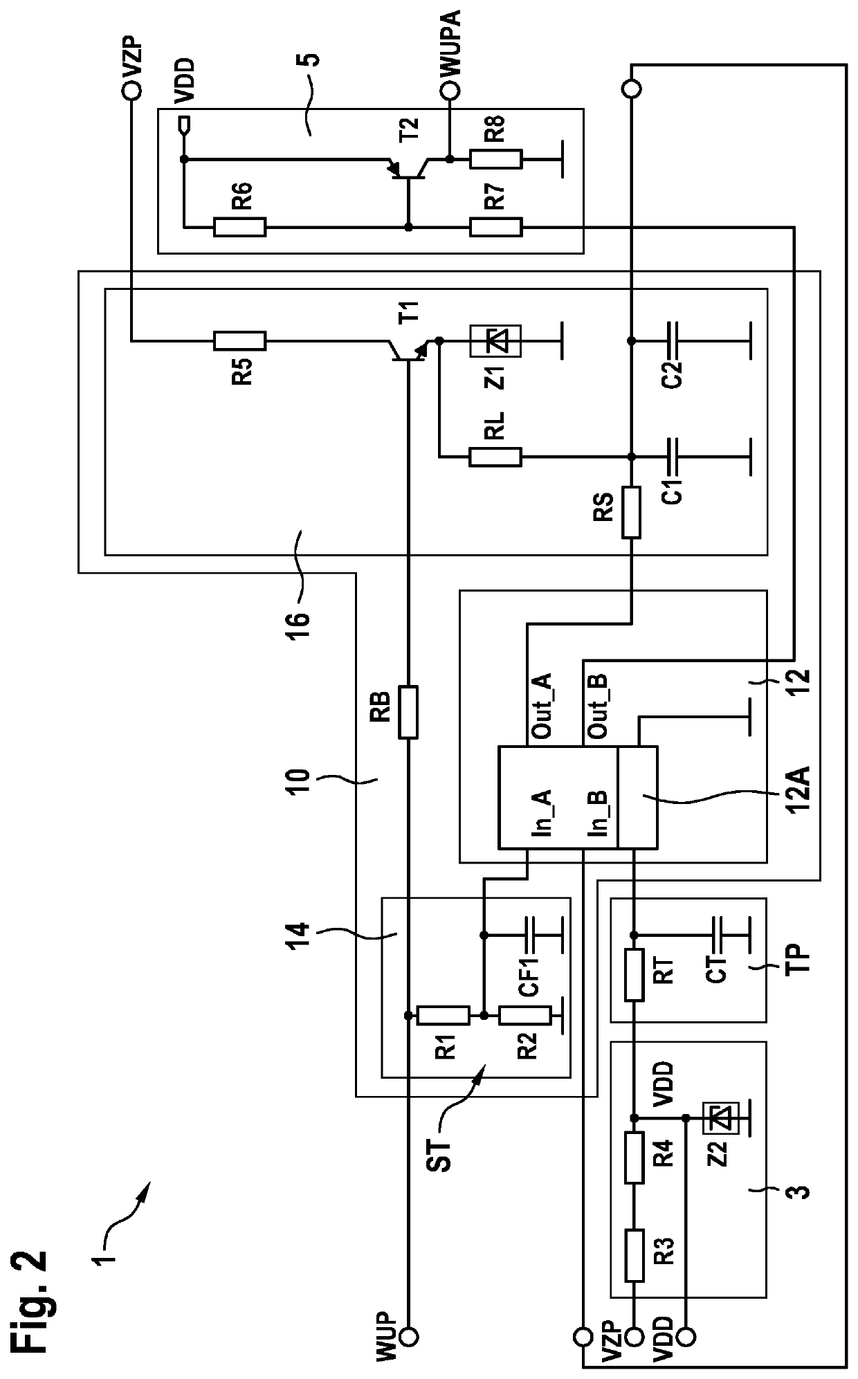
[0015]As is shown in FIGS. 1 and 2, the illustrated exemplary embodiment of a circuit 1 according to the present invention for processing a wake-up signal WUP, which is usable for the activation of electrical devices, includes an evaluation circuit 10 which checks an applied wake-up signal WUP for its validity; and an output driver circuit 5, which outputs a processed wake-up signal WUPA when evaluation circuit 10 evaluates an applied wake-up signal WUP as valid. Evaluation circuit 10 includes a comparator 12, which compares applied wake-up signal WUP to at least one threshold value for the evaluation. Evaluation circuit 10 includes an input circuit 14 and a switchable constant voltage source 16 via which at least one criterion is adjustable for the evaluation of applied wake-up signal WUP. In addition, comparator 12 is developed as a multi-channel, integrated comparator circuit 12A, the individual channels of integrated comparator circuit 12A evaluating one criterion of applied wak...


PUM


Abstract

A circuit for processing a wake-up signal, which is usable for activating electrical devices. The circuit includes an evaluation circuit, which checks an applied wake-up signal for its validity, and an output driver circuit, which outputs a processed wake-up signal when the evaluation circuit evaluates the applied wake-up signal as valid. The evaluation circuit has a comparator, which compares the applied wake-up signal to at least one threshold value for the evaluation. The evaluation circuit includes an input circuit and a switchable constant voltage source via which at least one criterion for evaluating the applied wake-up signal is adjustable in each case. The comparator is a multi-channel, integrated comparator circuit, and the individual channels of the integrated comparator circuit evaluating one criterion of an applied wake-up signal in each case.

Description

FIELD[0001]The present invention relates to a circuit for processing a wake-up signal.BACKGROUND INFORMATION[0002]Conventional circuits for processing what is known as a wake-up signal normally are developed as a component of an application-specific integrated circuit (ASIC) or as discrete circuits. The latter can be subdivided into analog and digital approaches. The task of such a circuit for processing a wake-up signal is to check the signals at the input of the circuit for validity, the signals being used for activating or waking electrical devices such as control units. Only signals having a certain amplitude or time duration, for instance, are detected as valid. This means that a corresponding wake-up request or a correspondingly processed wake-up signal will be output to the downstream electrical devices only if the wake-up signal is valid. Thus, if the applied wake-up signal is not detected as valid, then the electrical devices will not be activated.[0003]The conventional cir...

Claims


Application Information

Patent Timeline
Patent Type & Authority Applications(United States)
IPC IPC(8): H04W52/02
CPCH04W52/0229H04W52/028H04W52/0245Y02D30/70G01R19/16576Y02D30/50F02D41/02
Inventor SCHUMACHER, HARTMUTWANG, EUGENKOVACIC, LEONARDO
Owner ROBERT BOSCH GMBH
Why Eureka
Try Eureka