
SiO POWDER PRODUCTION METHOD AND SPHERICAL PARTICULATE SiO POWDER

a technology of production method, which is applied in the direction of silicon compounds, cell components, electrochemical generators, etc., can solve the problems of unavoidable increase in pulverization cost, excessive yield reduction, and difficult economic production of rounded spherical particulate sio powder on an industrial scale, and achieves low contamination. , the effect of high circularity and high efficiency

Pending Publication Date: 2021-10-07
OSAKA TITANIUM TECHNOLOGIES
View PDF3 Cites 0 Cited by
  • Summary
  • Abstract
  • Description
  • Claims
  • Application Information

AI Technical Summary

Benefits of technology

The present invention relates to a method for producing a high-quality SiO powder with low contamination levels and improved battery performance. The method involves leaving a portion of the SiO deposit on the deposition base and scraping off the remaining deposit to collect it. This results in efficient and economical production of rounded SiO powder with high circularity and small particle size. The resulting powder can be used as a negative electrode material for lithium ion batteries, leading to improved battery performance. The spherical particulate SiO powder produced using the method has characteristic features that are properly managed, resulting in improved battery performance when used as a negative electrode material. The spherical particulate SiO powder is also excellent in pulverizability, reducing the energy required for pulverization and lowering production costs.

Problems solved by technology

However, it is not easy to economically produce a rounded spherical particulate SiO powder on an industrial scale.
This is because when SiO gas generated by heating a mixture of silicon dioxide and silicon is cooled to be deposited, followed by fine pulverization to obtain an SiO powder, there is a large problem in that the obtained SiO powder is non-spherical particulate particles having corners accompanying pulverization, and a large amount of loss occurs in the process of screening rounded spherical particulate particles from the non-spherical particulate particles having corners, and consequently, the yield is excessively reduced.
However, an increase in the cost of pulverization is unavoidable, and the yield is still low.
Furthermore, cited reference 2 proposes, in particular, a technique of allowing particles to collide with each other, but an increase in the cost of pulverization is unavoidable.
In addition to these problems, there is an essential problem in that the more elaborately pulverization is performed, the more the chances and frequency of contact with a pulverization container and a pulverization medium are increased, resulting in an increase in the degree of contamination with an impurity in the obtained particles.
However, the SiO powder scraped off from the deposition base is scale-shaped particles, and rounded spherical particulate particles cannot be produced directly and continuously.
Furthermore, there is also a problem in that the particle diameter in the scale-shaped particle is increased.

Method used


Image

  • SiO POWDER PRODUCTION METHOD AND SPHERICAL PARTICULATE SiO POWDER
  • SiO POWDER PRODUCTION METHOD AND SPHERICAL PARTICULATE SiO POWDER
  • SiO POWDER PRODUCTION METHOD AND SPHERICAL PARTICULATE SiO POWDER

Examples


example 1-1

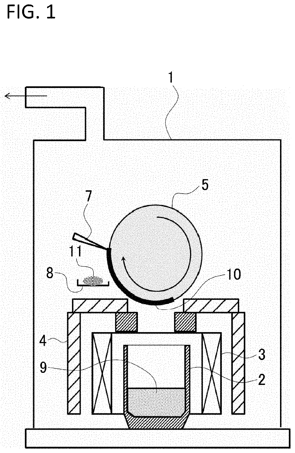
[0072]A mixture of Si and SiO2 (Si:O=1:1) as an SiO gas-generating raw material was loaded into a crucible as a reaction chamber, the crucible was set in a predetermined position inside a furnace body, after which the pressure inside the furnace body was reduced to 1 Pa, and the inside of the crucible was heated to 1300° C. to generate SiO gas. At the same time, the deposition base on the crucible was rotated while temperature control at 150° C. was performed to condense and deposit the SiO gas on the surface of the deposition base.

[0073]The growth rate d of the SiO deposit, that is, the film formation speed in the surface of the deposition base, was 4.8 μm / min at this time, and by adjusting the rotation speed of the deposition base, the scraping period n was made to be 2.4 min−1, and the ratio of both values d / n was made to be 2. Furthermore, a distance g from the surface of the deposition base to the tip end of the blade was 0.5 mm

[0074]In the position for scraping by the blade, t...

example 1-2

[0092]In Example 1-1, the rotation speed of the deposition base was reduced, the scraping period n was changed from 2.4 min−1 to 0.24 min−1, and accordingly, d / n was changed from 2 to 20. The other production conditions and examination methods were the same as those in Example 1-1. Various examination results are shown in Table 3 together with the production conditions of the SiO powder.

example 1-3

[0093]In Example 1-1, the rotation speed of the deposition base was increased, the scraping period n was changed from 2.4 min−1 to 48 min−1, and accordingly, d / n was changed from 2 to 0.1. The other production conditions and examination methods were the same as those in Example 1-1. Various examination results are shown in Table 3 together with the production conditions of the SiO powder.


PUM

PropertyMeasurementUnit
distanceaaaaaaaaaa
particle diameteraaaaaaaaaa

Abstract

[Problem to be solved] To produce an SiO powder having a rounded spherical particulate shape and a small particle diameter; and further having a low degree of impurity contamination, efficiently and economically.[Solution] A mixture of Si and SiO2 as an SiO gas generation raw material 9 is loaded into a crucible 2. The mixture in the crucible 2 is heated under a reduced pressure so as to generate SiO gas. The generated SiO gas is accumulated on a deposition base 5 rotating on the crucible 2. When SiO deposit 10 accumulated on the deposition base 5 is scraped off with a blade 7, a tip of the blade 7 is separated from a surface of the deposition base 5, and in a state in which a portion of the SiO deposit 10 accumulated on the deposition base 5 is left on the deposition base 5, the remaining SiO deposit 10 is scraped off by the blade 7 and collected as an SiO powder 11.

Description

TECHNICAL FIELD[0001]The present invention relates to a method for producing an SiO powder used as a negative electrode material for a lithium ion secondary battery and the like, and a spherical particulate SiO powder.BACKGROUND ART[0002]SiO is known to have a large electric capacity and to be an excellent negative electrode material for a lithium ion secondary battery. This SiO-based negative electrode material is formed into a thin film negative electrode by mixing an SiO powder, an electrically conductive auxiliary agent, and a binder with each other to obtain slurry, applying the slurry to a current collector made of a copper foil and the like, and drying thereof. The SiO powder herein is obtained by heating a mixture of silicon dioxide and silicon to generate SiO gas, and cooling the generated SiO gas to obtain deposit, followed by finely pulverizing the deposit.[0003]Patent Documents 1 to 3 mention that an SiO powder produced by such a deposition method is advantageous because...

Claims


Application Information

Patent Timeline
Patent Type & Authority Applications(United States)
IPC IPC(8): C01B33/18C23C16/01H01M4/48C23C16/56C23C16/40
CPCC01B33/182C23C16/01H01M2004/027C23C16/56C23C16/401H01M4/48C01B33/113H01M4/366C01P2004/03C01P2004/32C01P2004/61C01P2004/62Y02E60/10C23C14/0021C23C14/0005C23C14/588H01M4/62H01M10/0525H01M4/485H01M4/483C01P2002/54C01P2006/40C01P2004/02
Inventor TAKESHITA, KOHKIKASHITANI, YUSUKEFUJITA, TAKEHISAKIZAKI, SHINGO
Owner OSAKA TITANIUM TECHNOLOGIES
Features
  • Generate Ideas
  • Intellectual Property
  • Life Sciences
  • Materials
  • Tech Scout
  • Unparalleled Data Quality
  • Higher Quality Content
  • 60% Fewer Hallucinations
Learn More