Thermocline control method

Pending Publication Date: 2021-10-07
ETH ZZURICH
View PDF4 Cites 1 Cited by
  • Summary
  • Abstract
  • Description
  • Claims
  • Application Information

AI Technical Summary

Benefits of technology

[0006]The present invention provides a novel method of operating a thermal energy storage device by which the thermocline region can be controlled and the storage utilization factor can be further increased. The method

Problems solved by technology

While such devices are attractive from the cost perspective, they suffer from several drawbacks such as temperature degradation.
Another negative consequence of thermocline degradation is a limited utilization factor.
The larger the width of the therm

Method used


Image

  • Thermocline control method
  • Thermocline control method
  • Thermocline control method

Examples


Embodiment Construction

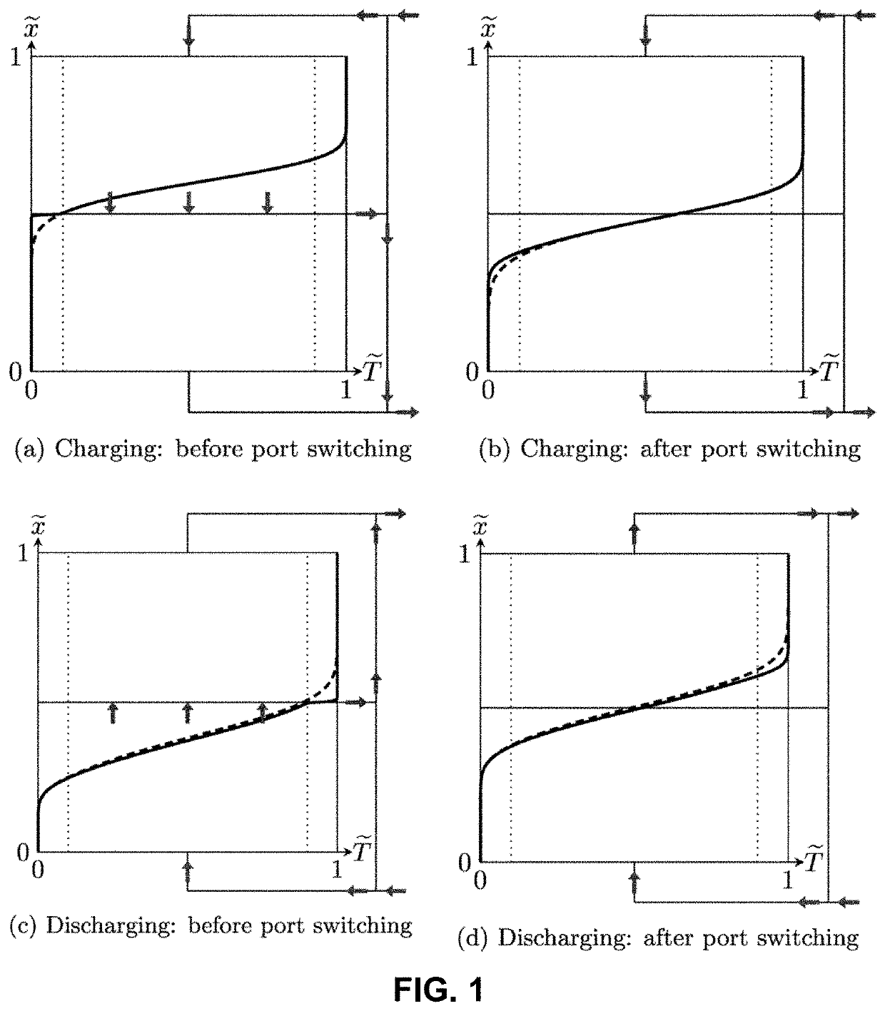
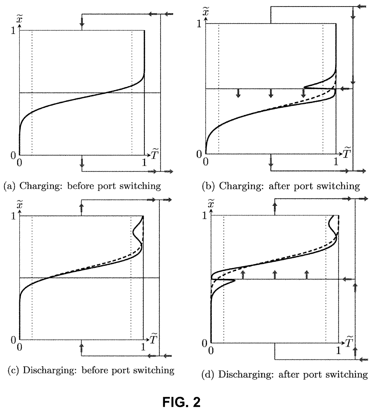
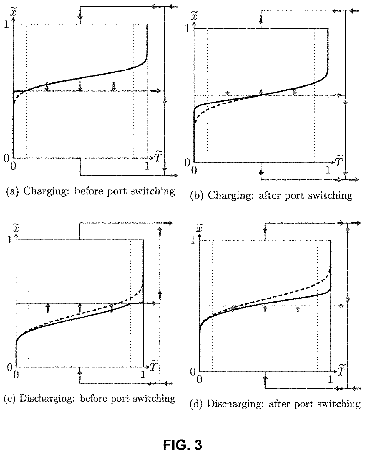
[0049]In the context of the present invention, the term “charging” of the thermal energy storage device means that heat transfer fluid having a temperature above an upper threshold temperature is added to the body of heat transfer fluid and conversely, the term “discharging” of the thermal energy storage device means that heat transfer fluid having a temperature below an lower threshold temperature is added to the body of heat transfer fluid.

[0050]It is an object of the present invention to provide a method of operating a thermal energy storage device comprising a body of heat transfer fluid, said body of heat transfer fluid comprising an upper temperature region comprising heat transfer fluid having a temperature above a upper threshold temperature, a lower temperature region comprising heat transfer fluid having a temperature below a lower threshold temperature and a thermocline region separating the upper and lower temperature regions and comprising heat transfer fluid having a t...


PUM


Abstract

The present invention to provide a method of operating a thermal energy storage device comprising a body of heat transfer fluid, said body of heat transfer fluid comprising an upper temperature region comprising heat transfer fluid having a temperature above a upper threshold temperature, a lower temperature region comprising heat transfer fluid having a temperature below a lower threshold temperature and a thermocline region separating the upper and lower temperature regions and comprising heat transfer fluid having a temperature above a lower threshold temperature and below an upper threshold temperature, wherein during charging of the thermal energy storage device, heat transfer fluid is removed from the thermocline region of the body of heat transfer fluid and when the temperature of the heat transfer fluid being removed from the thermocline region of the body of heat transfer fluid rises above a maximum temperature, said heat transfer fluid being removed is brought to a temperature equal to or below said maximum temperature, wherein the maximum temperature is above the lower threshold temperature and/or wherein during discharging of the thermal energy storage device, heat transfer fluid is removed from the thermocline region of the body of heat transfer fluid and when the temperature of the heat transfer fluid being removed from the thermocline region of the body of heat transfer fluid falls below a minimum temperature, said heat transfer fluid being removed is brought to a temperature equal to or above said minimum temperature, wherein said minimum temperature is below the upper threshold temperature.

Description

TECHNICAL FIELD[0001]The present invention relates to a method of operating a heat storage device comprising a body of heat transfer fluid by controlling the flow of heat transfer fluid from and into the upper hot layer, the lower cold layer and the intermediate thermocline region of the body of heat transfer during the charging and discharging.PRIOR ART[0002]Heat storage devices enable dispatchable thermal energy from intermittent solar energy, which thermal energy can then be used on demand to power multiple useful processes, such as for example to provide electricity via a heat engine coupled to a generator or to provide thermal energy for other applications such as thermochemical hydrocarbon fuel production. Heat storage devices are therefore expected to play an important role in the future.[0003]As of late, in particular single-tank heat storage devices such as for example heat storage devices using a packed bed of low-cost filler material in combination with a heat transfer fl...

Claims


Application Information

Patent Timeline
IPC IPC(8): F28D20/00
CPCF28D20/0039F28D2020/0082F28D2020/0069Y02E60/14
Inventor GEISSBÜHLER, LUKASHASELBACHER, ANDREAS CHRISTIAN
Owner ETH ZZURICH
Why Eureka
Try Eureka