Method and device for controlled filling and inspection of blast holes

a technology for controlled filling and inspection, applied in the direction of borehole/well accessories, survey, construction, etc., can solve the problems of large, non-detachable material pieces, and inability to reliably measure radar, etc., and achieve good results

Pending Publication Date: 2021-10-07
INDURAD
View PDF8 Cites 1 Cited by
  • Summary
  • Abstract
  • Description
  • Claims
  • Application Information

AI Technical Summary

Benefits of technology

[0014]The central idea of the invention is the detection of the absolute charge level of the explosive in the blasting borehole, in particular above the blasting borehole bottom, and since the detection of the charge stream of the explosive from the apparatus, in particular from a corresponding container of the apparatus, into the blasting borehole is anyway detected and monitored by the apparatus for charging the blasting borehole with explosive, the charge level of the explosive in the blasting borehole detected or monitored during the charging can be determined, that is what amount of explosive is located at what level above the blasting borehole bottom in the blasting borehole. The determination of the charge level takes place in that the substantially vertical distance of the radar head above the charge level of the explosive is measured and a calculation back to the charge level of the explosive in the blasting borehole can subsequently be carried out. The frequency range in which the at least one radar unit is operated is preferably above 3 GHz. A substantial advantage in the avoidance of the use of a ground penetrating radar (GPR) is the higher frequency since the construction dimensions of the radar unit having the associated antenna can thus also be configured as smaller, which is advantageous for the use of a radar in accordance with the invention since the latter should preferably be lowered into the borehole and small dimensions are thus advantageous.
[0015]Corresponding data for a controlled charging of blasting boreholes with explosive can thus be detected and provided, in particular to monitor the apparatus for charging the blasting borehole, and as a result to establish the required distribution of explosive over the height in the blasting borehole so that the subsequent blasting can be carried out with a correspondingly good result.

Problems solved by technology

However, disadvantageously, typical blasting borehole depths and curvatures are so large that a reliable radar measurement is no longer possible due to the Fresnel zone required for the propagation of the radar waves.
If the blasting borehole, for example, does not have the desired approximately cylindrical geometry, caused by resulting lateral chips in the jacket section of the blasting borehole, which is caused by the falling of broken material into the blasting borehole or by the running in of water, the charging can frequently not take place as is required for a desired blasting result.
As a result, large, non-detached material pieces are produced form the volume formation that have to be subsequently comminuted in a laborious manner, for example by mudcapping or by a hydraulic hammer.
It can equally occur that due to the falling of broken material into the blasting borehole too little explosive is charged in the deeper region of the blasting borehole and too much explosive is charged into the upper region of the blasting borehole with a constant filling quantity.
As a result, an escaping of blasting energy from the upper-side aperture opening is produced on a firing so that ultimately a satisfactory blasting result is also not achieved in this case since non-detached material regions that are too large remain at a greater depth of the blasting field.
A laborious subsequent comminution is also necessary here that is expensive and time intensive.
As a result, an exact charging of the blasting borehole for an optimum blasting is in particular necessary in a required distribution over the depth of the blasting borehole, which cannot be ideally ensured with previous means.

Method used


Image

  • Method and device for controlled filling and inspection of blast holes
  • Method and device for controlled filling and inspection of blast holes
  • Method and device for controlled filling and inspection of blast holes

Examples


Embodiment Construction

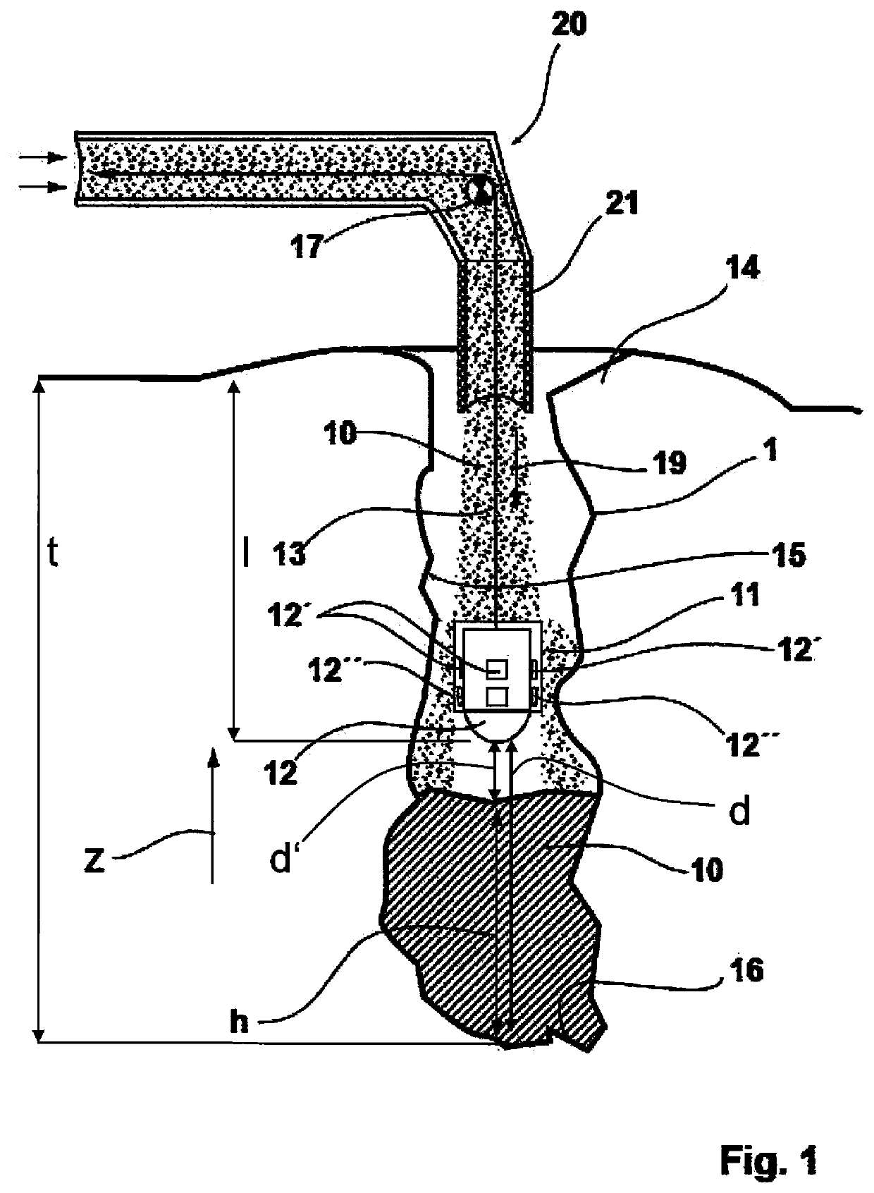
[0046]FIG. 1 schematically illustrates a cross-sectional view of a blasting borehole 1 that extends downwardly in a vertical direction, for example, in a blasting field starting from an upper-side aperture opening 14 on a base surface of the blasting field down to a blasting borehole base 16. The blasting borehole 1 can be charged with explosive 10 starting from the blasting borehole base 16, with the illustration showing a lower part region of the blasting borehole 1 already charged with explosive 10 with a charge level h. The explosive 10 is charged into the blasting borehole 1 via means 20 for charging said blasting borehole 1, with the means 20 being arranged at a vehicle, for example.

[0047]A radar head 11, that can be lowered into the blasting borehole 1 to a lowering depth l is fastened to a pulling means 13 for this purpose and the pulling means 13 is led through a covering tube 21 that forms a lower part of the means 20 for charging the blasting borehole 1 with explosive 10....


PUM


Abstract

A method and apparatus for controlled charging of blasting boreholes with a flowable/pourable explosive, in particular in open-cast mining, includes: providing a radar head with at least one radar unit operated in a non-rock penetrating frequency range; arranging the radar head on a pulling element; introducing the radar head into the borehole in that the radar head is lowered into the blasting borehole in an arrangement at the pulling means from an upper aperture opening of the blasting borehole; and detecting at least one measurement value comprising a base distance of the radar head from the blasting borehole base and/or a charge level distance to determine the charge level of the explosive in the blasting borehole; and/or comprising the shape of the jacket section over at least a portion of the depth of the blasting borehole by means of the operation of at least one of the radar units.

Description

CROSS REFERENCE TO RELATED APPLICATION[0001]This application claims priority to European Application No. 20 165 157.7 filed Mar. 24, 2020, the entire content of which is incorporated herein by reference.FIELD OF THE INVENTION[0002]The invention relates to a method and to an apparatus for the controlled charging of blasting boreholes with a flowable or pourable explosive, in particular in open-cast mining for the blasting of excavation volumes.BACKGROUND OF THE INVENTION[0003]US 2011 / 0006585 A1, for example, discloses a method for the inspection of blasting boreholes in open-cast mining to detect the condition of the blasting borehole so that a decision can be made in dependence on the condition whether the explosive is filled into the blasting borehole. The condition in this respect in particular relates to the temperature of the blasting borehole, above all in deeper regions, to avoid the blasting borehole having too high a temperature, in particular in the lower half, whereby the ...

Claims


Application Information

Patent Timeline
Patent Type & Authority Applications(United States)
IPC IPC(8): F42D1/10E21B47/047E21B47/26
CPCF42D1/10E21B7/007E21B47/26E21B47/047F42D3/04E21B2200/20E21B47/01E21B47/024E21B47/09
Inventor WINKEL, REIK
Owner INDURAD
Why Eureka
Try Eureka