
Nozzle structure applying RF heating device for 3D printer

Active Publication Date: 2021-10-21
WAVEPIA CO LTD
View PDF0 Cites 0 Cited by
  • Summary
  • Abstract
  • Description
  • Claims
  • Application Information

AI Technical Summary

Benefits of technology

The present invention is a nozzle structure for a 3D printer that uses an RF heating device. The nozzle structure is designed to effectively melt material using the RF frequency and maintain a proper temperature at the nozzle by minimizing heat transfer to the body of the printer. This structure also reduces the preheating time of the printer and lowers the precise temperature and power consumption for material melting. The nozzle connection unit is made of metal material and transfers heat to the nozzle neck unit, while the separation unit is made of heat insulating material and prevents heat transfer to the nozzle neck unit.

Problems solved by technology

On the other hand, the cutting-type method is a method of outputting a three-dimensional shape by cutting a bulk block like carving, and although it is advantageous in that a finished product is more precise than those of the stacked-type method, there is a disadvantage in that the material is excessively consumed, a shape with a hollow inside like a cup is difficult to manufacture, and a coloring work should be separately performed.
However, there is a disadvantage in that durability and heat resistance of output products are low and manufacturing cost is high by the nature of manufacturing, compared with 3D printers of other methods.
Although it is advantageous in that the output speed is high and it is possible to overcome the limit of material properties as a variety of materials are used, there is a disadvantage in that a printable size of a product is limited according to the size of a powder block, and the manufacturing cost is high compared with 3D printers of other methods.
Although there is a disadvantage in that the surface of a molded product is rough and the output speed is low compared with other methods by the nature of the method of stacking and molding a material melted in the nozzle, while the molded product has advantages of excellent durability owing to high strength and humidity resistance, the fused deposition modeling (FDM) method is most widely used currently among the 3D printers as the structure is simple and the price of thermoplastic material, which is a molding material, is low.
A 3D printer of the fused deposition modeling (FDM) employing an induction heating apparatus of the prior art has a problem in that the preheating time is excessively increased according to a set temperature, and power consumption is excessively increased.

Method used


Image

  • Nozzle structure applying RF heating device for 3D printer
  • Nozzle structure applying RF heating device for 3D printer
  • Nozzle structure applying RF heating device for 3D printer

Examples


Embodiment Construction

[0033]Hereinafter, a nozzle structure applying an RF heating device for a 3D printer according to an embodiment of the invention will be described in detail with reference to the accompanying drawings.

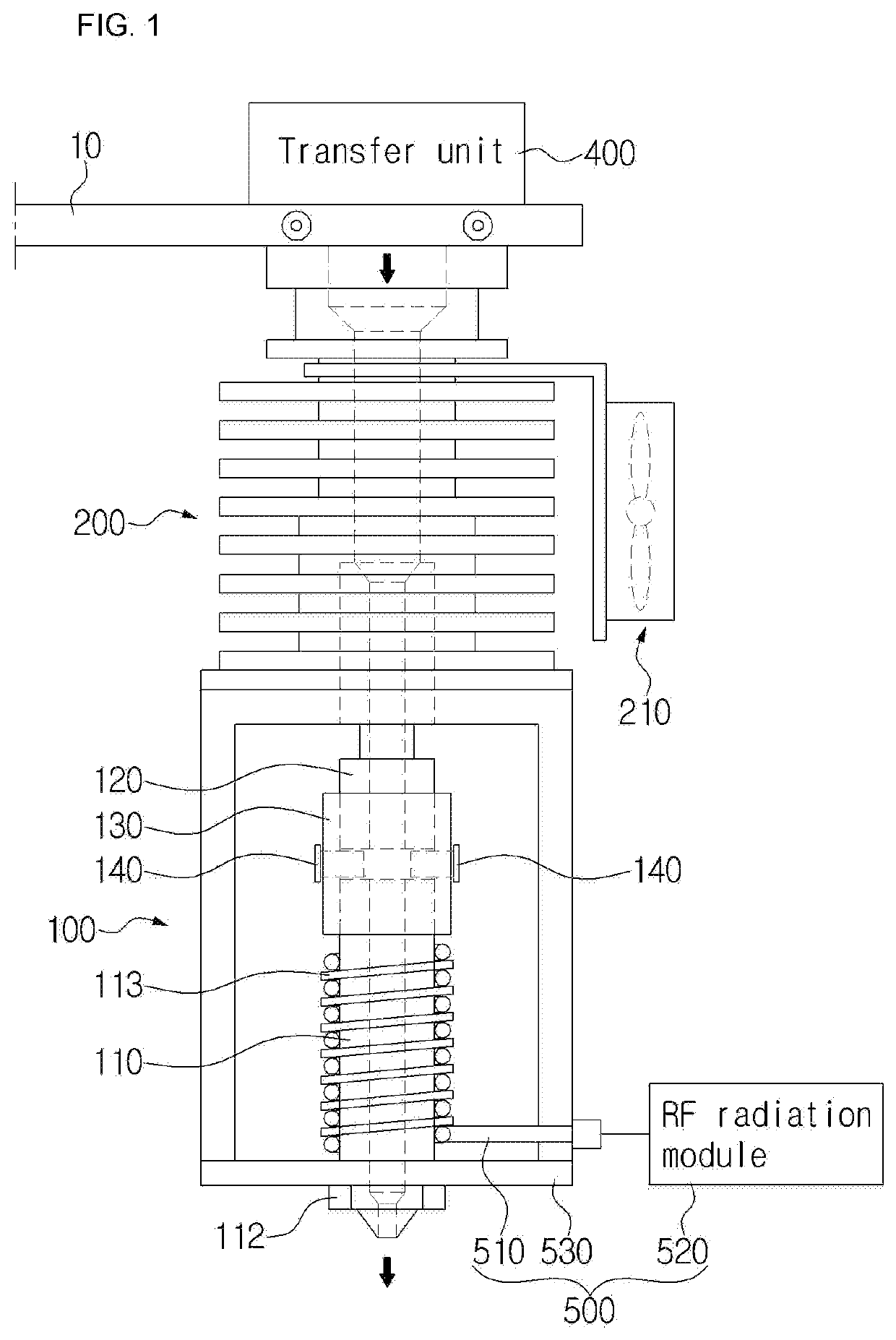
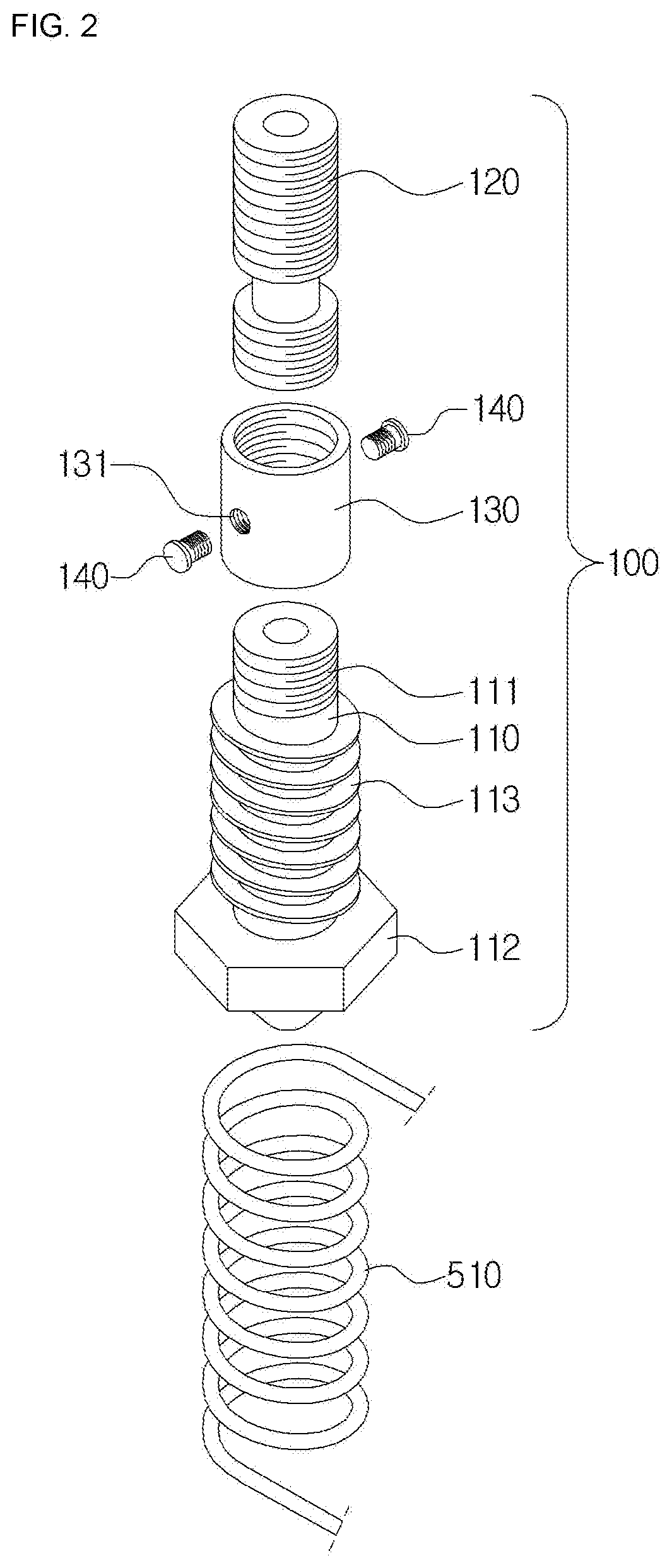
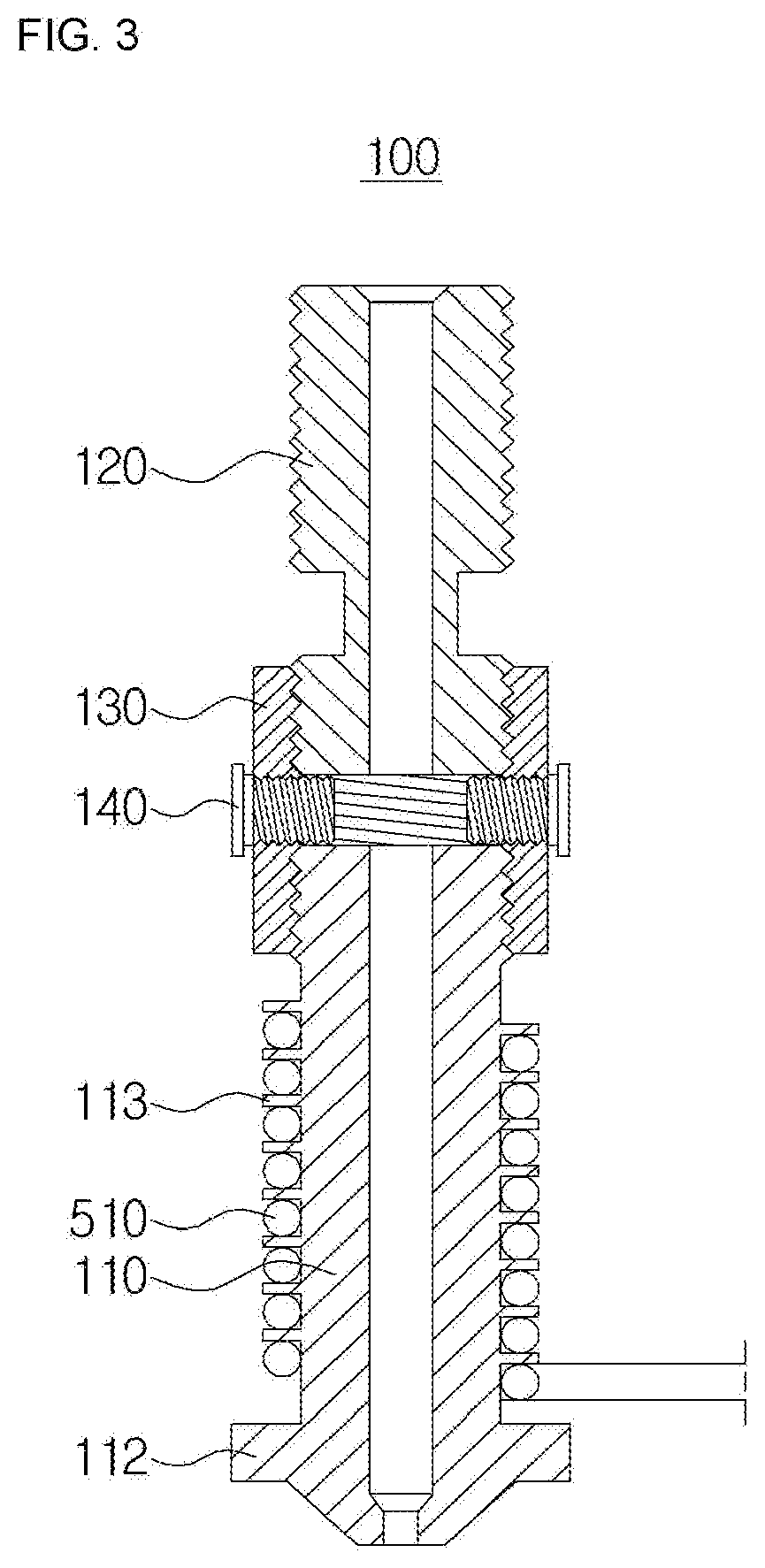
[0034]As shown in FIGS. 1 to 6, a nozzle structure applying an RF heating device for a 3D printer includes a nozzle unit 100 for melting and discharging an inflowing material using heat transferred from the outside, a transfer unit 400 for transferring the material to the nozzle unit 100, an RF nozzle heating unit 500 for heating up the nozzle unit 100 using a high frequency so that the material is melted in the nozzle unit 100, and a cooling unit 200 for cooling down the heat discharged from the nozzle unit 100 to the outside.

[0035]First, the material may be configured of a thermoplastic.

[0036]The nozzle unit 100 includes a nozzle 110 having a screw unit 111 formed at an upper portion, a nozzle neck unit 120 having threads formed on the outer circumferential surface to be fixed to the...


PUM

PropertyMeasurementUnit
Temperatureaaaaaaaaaa
Structureaaaaaaaaaa
Frequencyaaaaaaaaaa

Abstract

A nozzle structure applying an RF heating device for a 3D printer, the structure includes: a nozzle unit for melting and discharging an inflowing material using heat transferred from the outside; a transfer unit for transferring the material to the nozzle unit; an RF nozzle heating unit for heating up the nozzle unit using a high frequency so that the material is melted in the nozzle unit; and a cooling unit for cooling down the heat discharged from the nozzle unit 100 to the outside.

Description

BACKGROUND[0001]The present invention relates to a nozzle structure applying an RF heating device for a 3D printer, which can effectively melt a material using an RF frequency at the nozzle of the 3D printer, and maintain a proper temperature at the nozzle by minimizing transfer of heat, which is provided to the nozzle to melt the material, to the body.[0002]A 3D printer is a system for outputting a three-dimensional product of an input drawing as if a printer prints a character or a picture.[0003]According to a method of outputting a three-dimensional shape, 3D printers like this are largely divided into a stacking-type method of piling up one layer after another, and a cutting-type method of cutting out a bulk block.[0004]The stacking-type method is a method of outputting a three-dimensional shape by stacking powder, plastic liquid or plastic yarn in layers of 0.01 to 0.08 mm, and the thinner the layer, a more precise shape may be obtained.[0005]On the other hand, the cutting-type...

Claims


Application Information

Patent Timeline
IPC IPC(8): B29C64/209B29C64/295B29C64/30
CPCB29C64/209B33Y30/00B29C64/30B29C64/295B29C64/118B33Y10/00B29C64/364H05B6/68H05B6/80B33Y40/00
Inventor LEE, SANG-HUN
Owner WAVEPIA CO LTD
Learn More