Analysis device

an analysis device and a technology of ionization capability, applied in the direction of material analysis, instruments, mass spectrometers, etc., can solve the problems of unfavorable quantitative measurement of adversely affecting measurement, and difficult to quantitatively measure specimen gas components with a conventional analysis device. , to achieve the effect of stabilizing the ionization capability of the analysis device and stabilizing the results of analysis

Active Publication Date: 2021-10-28
SHARP KK
View PDF5 Cites 1 Cited by
  • Summary
  • Abstract
  • Description
  • Claims
  • Application Information

AI Technical Summary

Benefits of technology

[0008]The power source and the controller are so provided as to allow application of a voltage between the bottom electrode and the surface electrode. As a result, it is possible to cause the electron emission element to emit electrons, and convert an air component into anions to generate primary ions. An ion molecule reaction of the primary ions with a component to be detected in a specimen gas makes it possible to convert the component to be detected into anions.
[0010]The controller is so provided as to regulate, based on the current waveform, the voltage applied between the bottom electrode and the surface electrode. The peak height or the peak area of the current waveform represents the amount of ions arriving at the collector. Consequently, the generation amount of primary ions, for instance, which amount varies depending on environmental conditions, such as the temperature and the humidity, and the life characteristics of the electron emission element, is stabilized by regulating, based on the current waveform, the voltage applied to the electron emission element. As a result, it is possible to stabilize the ionization capability of the analysis device and stabilize the results of analysis. It is also possible to quantitatively measure the component to be detected with the analysis device according to the present invention.

Problems solved by technology

The radioactive substance, however, needs caution and supervision peculiar to the handling of such substance, and the corona discharge releases a high energy during the ionization to generate unnecessary ions and may change the substance to be measured in quality to adversely affect the measurement.
In a method using deep ultraviolet, an ionizable subject is unfavorably restricted by the wavelength of an ultraviolet ray.
In addition, it is difficult to quantitatively measure a specimen gas component with a conventional IMS analysis device.

Method used


Image

  • Analysis device
  • Analysis device
  • Analysis device

Examples


first embodiment

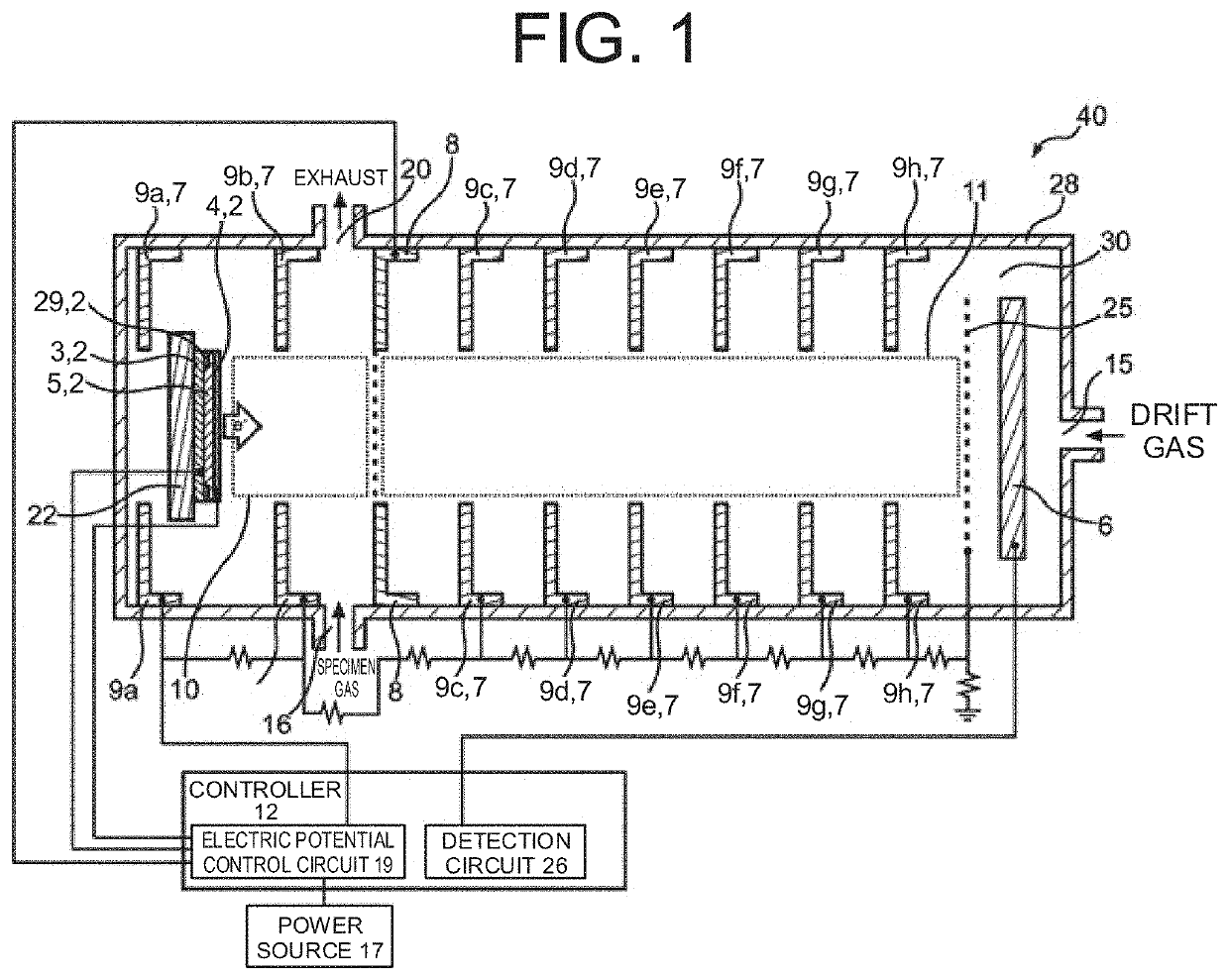
[0036]FIG. 1 is a schematic cross-sectional view of an analysis device according to the present embodiment. FIG. 1 includes a block diagram illustrating an electric configuration of an analysis device 40.

[0037]The analysis device 40 according to the present embodiment includes an electron emission element 2, a collector 6, an electric field former 7, a power source 17, and a controller 12. The electron emission element 2 includes a bottom electrode 3, a surface electrode 4, and an intermediate layer 5 arranged between the bottom electrode 3 and the surface electrode 4.

[0038]The power source 17 and the controller 12 are so provided as to allow application of a voltage between the bottom electrode 3 and the surface electrode 4. The electric field former 7 is so provided as to form an electric field in an ion movement region 11 where anions directly or indirectly generated by electrons emitted from the electron emission element 2 move toward the collector 6. The collector 6 and the con...

second embodiment

[0102]In the first embodiment, in which a peak waveform derived from the primary ions in the state, where the specimen gas is not introduced into the ionization region 10, is measured and the calibration process is performed before the component to be detected in the specimen gas is measured, calibration needs to be made for each measurement, which makes operations complicated and a continuous measurement difficult. In order to solve such problem, in a second embodiment, feedback control is so performed as to make the total peak area of the current waveform of the recovery current constant in a continuous measurement of the specimen gas. Making the total peak area of the current waveform of the recovery current constant is equivalent to making the total charge amount of anions having arrived at the collector 6 constant.

[0103]In the second embodiment, the controller 12 is so provided as to regulate the voltage applied between the bottom electrode 3 and the surface electrode 4 so that...

third embodiment

[0112]In a third embodiment, the controller 12 is so provided as to change a target value for feedback control so as to regulate the measurement sensitivity or the ionization capability of the analysis device 40.

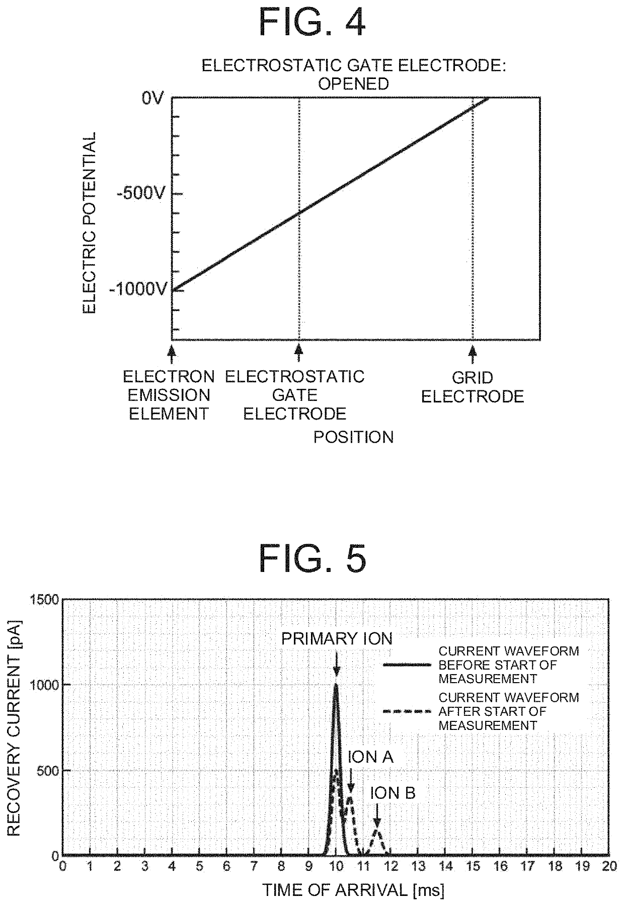
[0113]If the concentration of the component to be detected, which is contained in the specimen gas, is low, a peak of anions derived from the component to be detected may not appear in the current waveform after the start of measurement in an initial phase and the peak of the primary ions may only appear. As an example, such a current waveform as a solid line waveform in FIG. 11 is measured. In that case, the amount of the component to be detected in the specimen gas is extremely slight in itself, so that a peak of anions derived from the component to be detected scarcely appears even if the detection sensitivity of the detection circuit 26 is increased.

[0114]In the third embodiment, if a peak of anions derived from the component to be detected does not appear in the current...


PUM

PropertyMeasurementUnit
thicknessaaaaaaaaaa
thicknessaaaaaaaaaa
thicknessaaaaaaaaaa

Abstract

An analysis device includes an electron emission element, a collector, an electric field former, a power source, and a controller. The electron emission element includes a bottom electrode, a surface electrode, and an intermediate layer arranged between the bottom electrode and the surface electrode. The power source and the controller allow application of a voltage between the bottom electrode and the surface electrode. The electric field former forms an electric field in an ion movement region where anions directly or indirectly generated by electrons emitted from the electron emission element move toward the collector. The collector and the controller allow measurement of a current waveform of an electric current made to flow by arrival of anions at the collector. The controller regulates, based on the current waveform, a voltage applied between the bottom electrode and the surface electrode.

Description

BACKGROUND OF THE INVENTIONField of the Invention[0001]The present invention relates to an analysis device of an ion mobility-spectrometric type.Description of the Background Art[0002]Ion mobility spectrometry (IMS) is a technology for conducting a component analysis of a substance of interest by ionizing the substance and measuring the ion mobility in a gas, and uses, as an ionization source, a radioactive substance, corona discharge, deep ultraviolet, and the like. The radioactive substance, however, needs caution and supervision peculiar to the handling of such substance, and the corona discharge releases a high energy during the ionization to generate unnecessary ions and may change the substance to be measured in quality to adversely affect the measurement. In a method using deep ultraviolet, an ionizable subject is unfavorably restricted by the wavelength of an ultraviolet ray.[0003]As an ionization method solving the problems as above, a soft ionization method using an electr...

Claims


Application Information

Patent Timeline
Patent Type & Authority Applications(United States)
IPC IPC(8): H01J49/28G01N27/622
CPCH01J49/282G01N27/622G01N27/624
Inventor MORITANI, MASAMITSUKYUHKEN, KATSUHIKOKOMARU, SHOHEIIWAMATSU, TADASHIMORIMOTO, SATOSHI
Owner SHARP KK
Why Eureka
Try Eureka