Dual-Polarized Duplex Antenna and Dual-Band Base Station Antenna Array Composed Thereof

a dual-polarized, duplex antenna technology, applied in the direction of individual energised antenna arrays, polarised antenna unit combinations, array feeding systems, etc., can solve the problems of increased system size, loss and cost, and inability to solve the insertion loss introduced by the duplexer, etc., to achieve high gain in the antenna passband, good directional radiation performance, and stable radiation pattern

Active Publication Date: 2021-10-28
SOUTH CHINA UNIV OF TECH
View PDF0 Cites 5 Cited by
  • Summary
  • Abstract
  • Description
  • Claims
  • Application Information

AI Technical Summary

Benefits of technology

[0006]The antenna realizes functions of dual polarization and duplex communication without any additional size, and has higher gain, less insertion loss, better polarization isolation and cross-band isolation, thereby meeting the basic requirements of communication system.
[0023](2) The antenna has high gain in antenna passband, good directional radiation performance, stable radiation pattern, remarkable out-of-band suppression, and good frequency selectivity characteristic;
[0025](4) A PCB structure is adopted, which is easy to be manufactured and installed.

Problems solved by technology

However, this mode requires a 50-Ω connecting line and a corresponding matching network, which will undoubtedly increase the size of the system, meanwhile the loss and cost will also increase.
However, input and output ports of the antenna still exist in a duplexer circuit, so the insertion loss introduced by the duplexer cannot be solved.
However, the gain of the antenna is low.
Moreover, these duplex antennas are single-polarized, and it is also difficult to expand the designed structure into a dual-polarized radiation mode.
However, both ways will increase the size and loss of the system.

Method used


Image

  • Dual-Polarized Duplex Antenna and Dual-Band Base Station Antenna Array Composed Thereof
  • Dual-Polarized Duplex Antenna and Dual-Band Base Station Antenna Array Composed Thereof
  • Dual-Polarized Duplex Antenna and Dual-Band Base Station Antenna Array Composed Thereof

Examples


embodiment

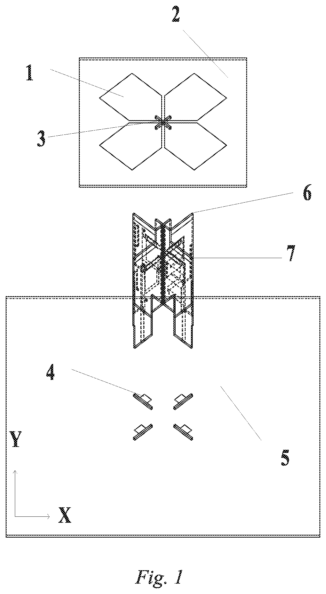
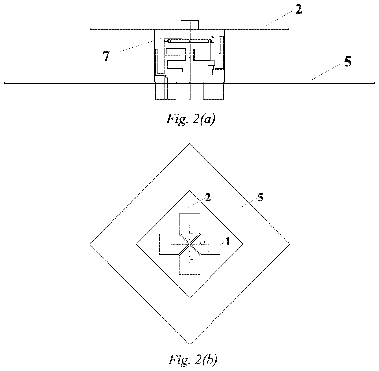
[0039]As shown in FIG. 1, FIG. 2(a), FIG. 2(b), FIG. 3(a), FIG. 3(b), FIG. 3(c) and FIG. 3(d), a dual-polarized duplex antenna comprises a top-layer dielectric substrate 2, wherein a metal reflective ground plate 5 is horizontally placed below the top-layer dielectric substrate 2, and four dipole arms 1 are horizontally placed on the upper surface of the top-layer dielectric substrate, with two of the dipole arms at +45° to form +45° polarized radiation; the other two dipole arms at −45° to form −45° polarized radiation, and the four dipole arms being in central symmetry with respect to the top-layer dielectric substrate; and a coordinate axis is as shown in FIG. 1.

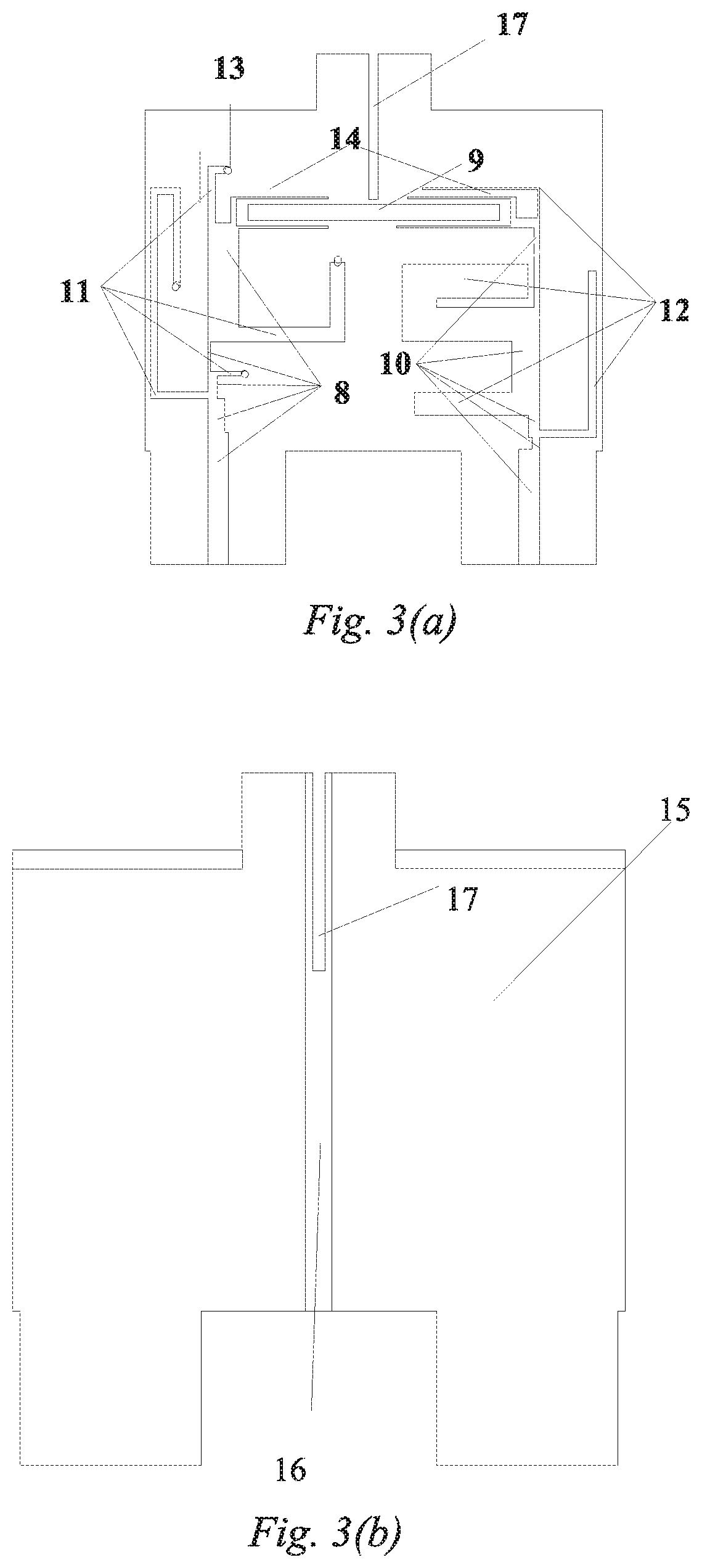
[0040]Vertically-placed duplex baluns 6 and 7 which achieve duplex operation and ensure good isolation of two frequency bands are placed between the top-layer dielectric substrate and the metal reflective ground plate. There are two duplex baluns, and the two duplex baluns have the same structure and are placed at +45° an...


PUM

PropertyMeasurementUnit
impedanceaaaaaaaaaa
frequencyaaaaaaaaaa
frequencyaaaaaaaaaa

Abstract

A dual-polarized duplex antenna includes a top-layer dielectric substrate; a metal reflective ground plate below the top-layer dielectric substrate; vertically-placed duplex baluns for duplexing operation between the top-layer dielectric substrate and the metal reflective ground plate; and four dipole arms horizontally printed on an upper surface of the top-layer dielectric substrate. Each of the duplex balun includes a vertical dielectric substrate, a balun feedline printed on a front side of the vertical dielectric substrate, and a ground plane with a printed slot line printed on a reverse side of the vertical dielectric substrate. The balun feedline includes a low-pass filter, a high-pass filter and a microstrip feeding structure serving as a connection. The low-pass filter and the high-pass filter are located on two sides of the slot line, and are connected together by the microstrip feeding structure.

Description

TECHNICAL FIELD[0001]The present invention relates to the field of wireless mobile communications, and in particular, to a dual-polarized duplex antenna and a dual-band base-station antenna array composed thereof.BACKGROUND ART[0002]Transceiving duplexing is a common method in mobile communications. In a communication system, for the implementation of transceiving duplexing, the most important thing is to solve the problem of mutual interference between transceiving channels. In frequency division duplexing, different transceiving channels occupy different frequencies, and a mode of directly cascading a duplexer with an antenna is often adopted to increase the isolation between the transceiving channels, thereby reducing interference. However, this mode requires a 50-Ω connecting line and a corresponding matching network, which will undoubtedly increase the size of the system, meanwhile the loss and cost will also increase.[0003]In order to achieve high integration of the antenna wi...

Claims


Application Information

Patent Timeline
Patent Type & Authority Applications(United States)
IPC IPC(8): H01Q21/06H01Q19/10H01Q21/00H01Q15/24H01Q15/00
CPCH01Q21/061H01Q19/104H01Q15/0013H01Q15/24H01Q21/0006H01Q1/38H01Q1/48H01Q1/50H01Q1/52H01Q21/26H01Q1/246H01Q5/50Y02D30/70
Inventor ZHANG, XIUYINWU, YUFENGCAO, YUNFEIDUAN, WENZHANG, YAO
Owner SOUTH CHINA UNIV OF TECH
Why Eureka
Try Eureka