Test system for compact multi-band, near-field to far-field and direct far-field

Pending Publication Date: 2021-11-04
EMITE ING SL
View PDF0 Cites 5 Cited by
  • Summary
  • Abstract
  • Description
  • Claims
  • Application Information

AI Technical Summary

Problems solved by technology

This approach, known as near-field-to-far-field (NFTF), requires a near-to-far-field transformation, a very accurate positioning of a probe and it is very time-consuming, limiting the angular range of the calculated patterns in practice.
Several test systems using one of the three methods can be found in the literature, but to date there is no invention that can use all three approaches in a simultaneous manner as all of them employ a single wavefront propagating towards the antenna under test, and consequently, using more than one system would cause the physical components of one approach interfere or block the wavefronts created by other approaches.
As a result, time and labour costs are introduced for setting up, aligning, and storing the direct far-field feed source antenna in such a setup.
Also, facility resources are r

Method used


Image

  • Test system for compact multi-band, near-field to far-field and direct far-field
  • Test system for compact multi-band, near-field to far-field and direct far-field
  • Test system for compact multi-band, near-field to far-field and direct far-field

Examples


example 1

mpact, Near-Field-to-Far-Field and Direct Far-Field Test Range where all Wavefronts are Planar

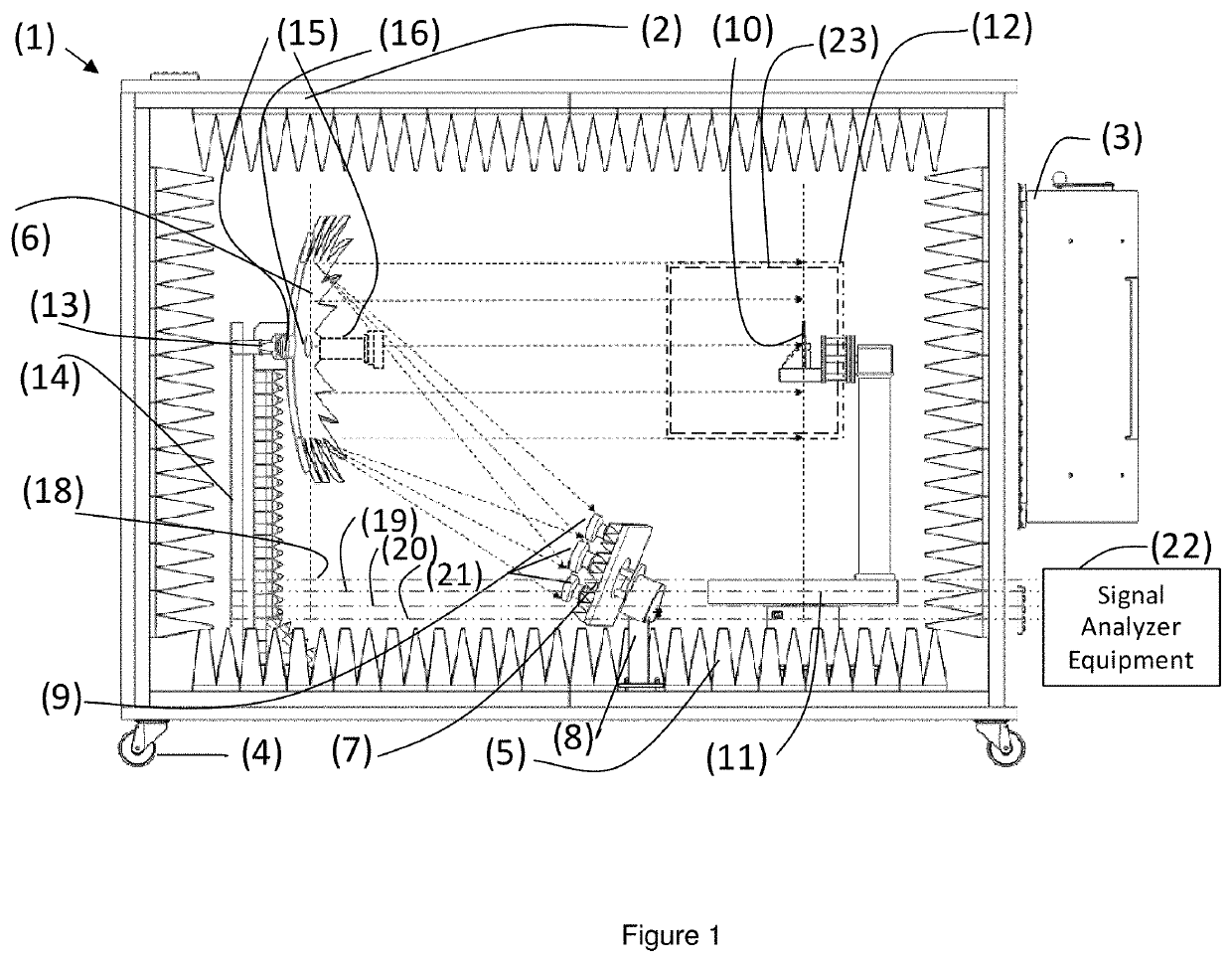
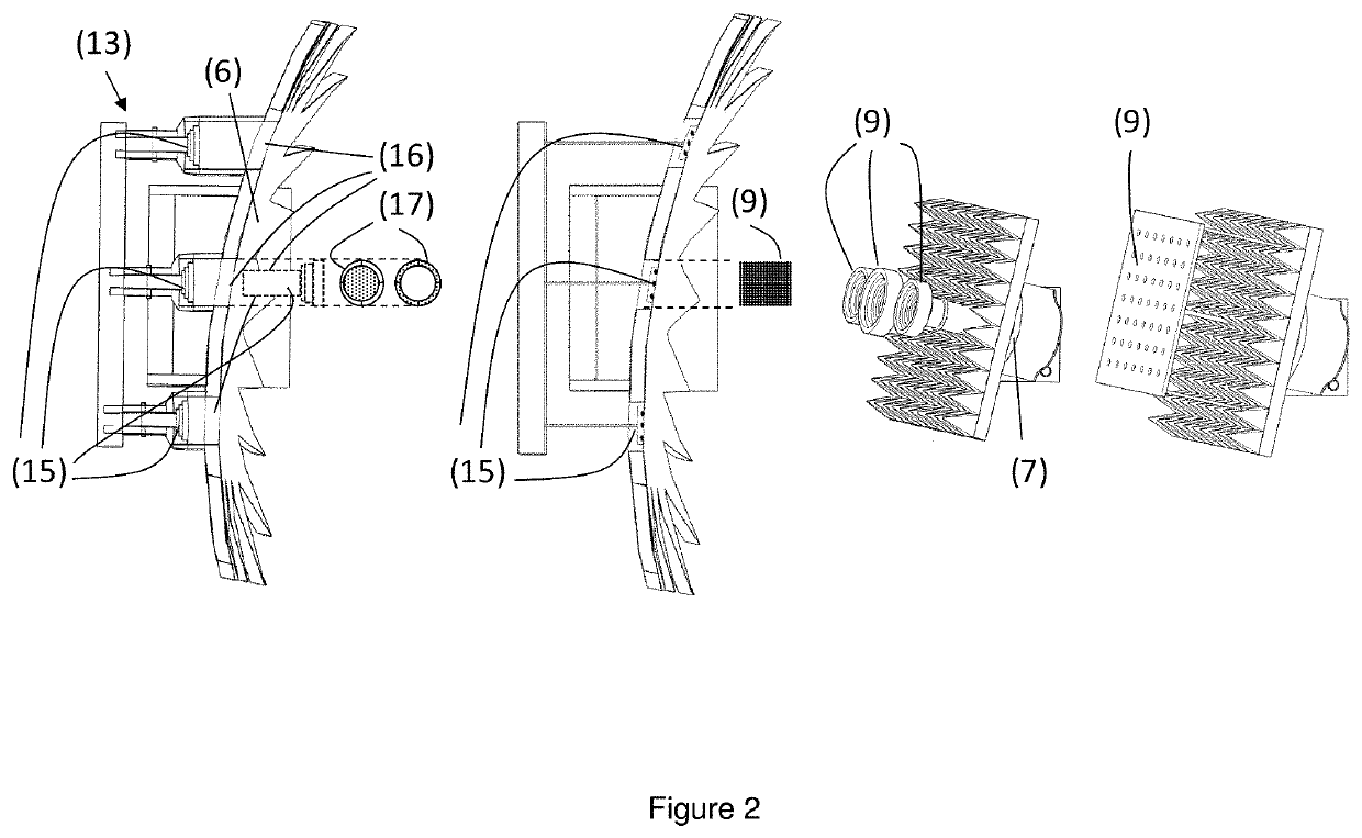
[0026]In the favourite mode of the hybrid compact, near-field-to-far-field and direct far-field test range system the number of dual-polarized antenna elements at the primary feed source antenna set is one of the corrugated circular waveguide horn or printed array type, operating at the 5G FR2 mmWave frequency range, the number of antenna elements at the secondary feed source antenna set is one, of the type corrugated circular waveguide horn or printed array type, operating at the 5G Sub-6 GHz frequency range, the offset reflector has serrated edges with dimension of 1.2 m from tip to tip and the quiet test zone is a cylinder of 30 cm long by 30 cm in diameter, in which up to four different wavefronts in their far-field are provided. In this favourite mode of the hybrid compact, near-field-to-far-field and direct far-field test range system all wavefronts are in the far-field, and no near-t...

example 2

mpact, Near-Field-to-Far-Field and Direct Far-Field Test Range where not all Wavefronts are Planar

[0032]In the favourite mode of the hybrid compact, near-field-to-far-field and direct far-field test range system the number of dual-polarized antenna elements at the primary feed source antenna set is three of the corrugated circular waveguide horn or printed array type, operating at the 5G FR2 mmWave frequency range, the number of antenna elements at the secondary feed source antenna set is one, of the type corrugated circular waveguide horn or printed array type, operating at the 5G Sub-6 GHz frequency range, the offset reflector has serrated edges with dimension of 1.5 m from tip to tip and the quiet test zone is a cylinder of 60 cm long by 60 cm in diameter, in which up to eight different wavefronts in either their far-field or near-field are provided. In this favourite mode of the hybrid compact, near-field-to-far-field and direct far-field test range system not all wavefronts are...


PUM


Abstract

The invention discloses a hybrid compact, near-field-to-far-field and direct-far-field test system in an anechoic chamber. It comprises a curved reflector with its primary feed antenna set situated on a lateral side and pointing towards it, a secondary feed antenna set pierced to the reflector or in front of it, and one or several sets of antennas or devices under test (AUT/DUT), and their 3D turntable tower placed at a quiet zone, for which roll, elevation and azimuth can change. In a receive process, the primary antenna set transmits several signals towards the reflector, which reflects these signals towards the quiet zone in the form of planar wavefronts. The secondary antenna set also transmits several signals, but directly towards the quiet zone in spherical wavefronts. The AUT/DUT receives all these signals simultaneously. Through reciprocity, a similar measurement process for transmission can be performed.

Description

FIELD OF INVENTION[0001]This invention relates generally to antenna and device test systems, and more particularly, to a hybrid compact (CATR), near-field to far-field (NFTF) and direct far-field (DFF) test range simultaneously employing a near-field test range, direct far-field test range and a compact antenna test range.BACKGROUND OF THE INVENTION[0002]Over the air testing of wireless devices typically employ test systems similar to those used for measuring antennas. Three different methods exist for measuring the radiation pattern of an antenna set or devices within an anechoic chamber. The oldest approach is to illuminate the AUT or DUT with the electromagnetic wave coming from a distant line-of-sight source. The electromagnetic field expanding into space from a point source is spherical when in the vicinity of the source, known as near-field, but at large distances in terms of wavelengths from the illuminating antenna, the wavefront can be observed as essentially planar, with u...

Claims


Application Information

Patent Timeline
IPC IPC(8): G01R29/10H01Q13/02H01Q21/24H01Q1/38H01Q15/14
CPCG01R29/105H01Q13/0208H04B7/0413H01Q1/38H01Q15/14H01Q21/24G01R29/0871G01R29/0821H04B17/19H04B17/29
Inventor SANCHEZ HERNANDEZ, DAVID AGAPITO
Owner EMITE ING SL
Why Eureka
Try Eureka